[0008]One aspect of the invention is to create a device for the plasma-activated vapor coating of large surfaces with which device a plasma with
high plasma density and a high uniformity of the plasma is produced perpendicular to the movement direction of the substrates in a simple and cost-effective manner.
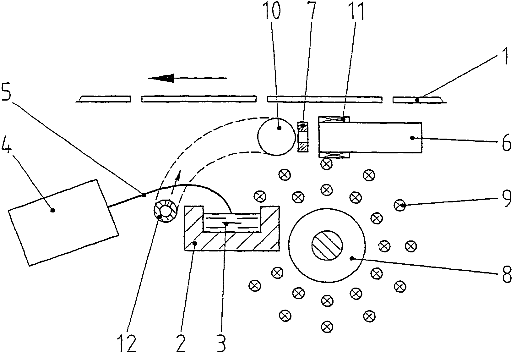
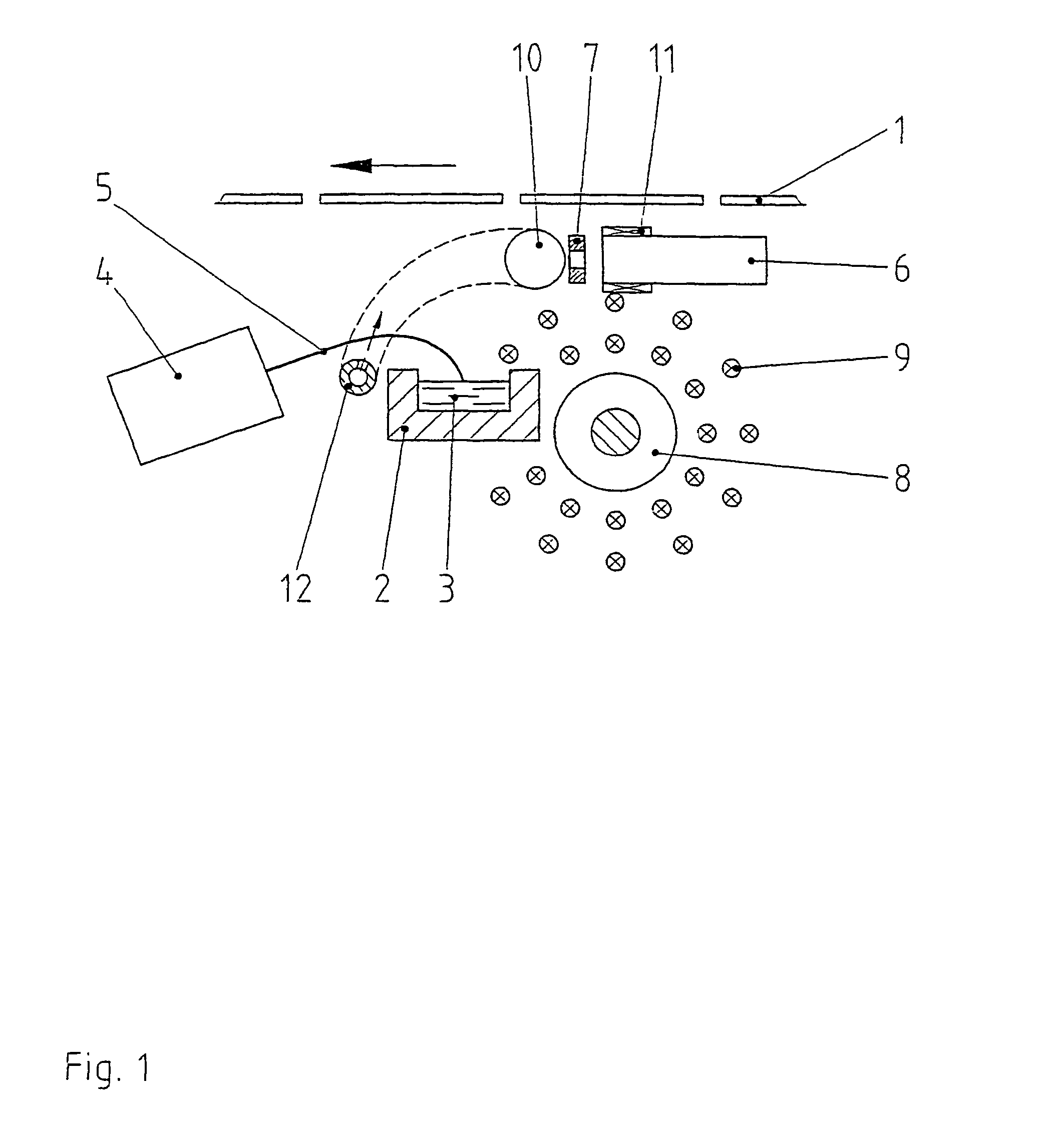
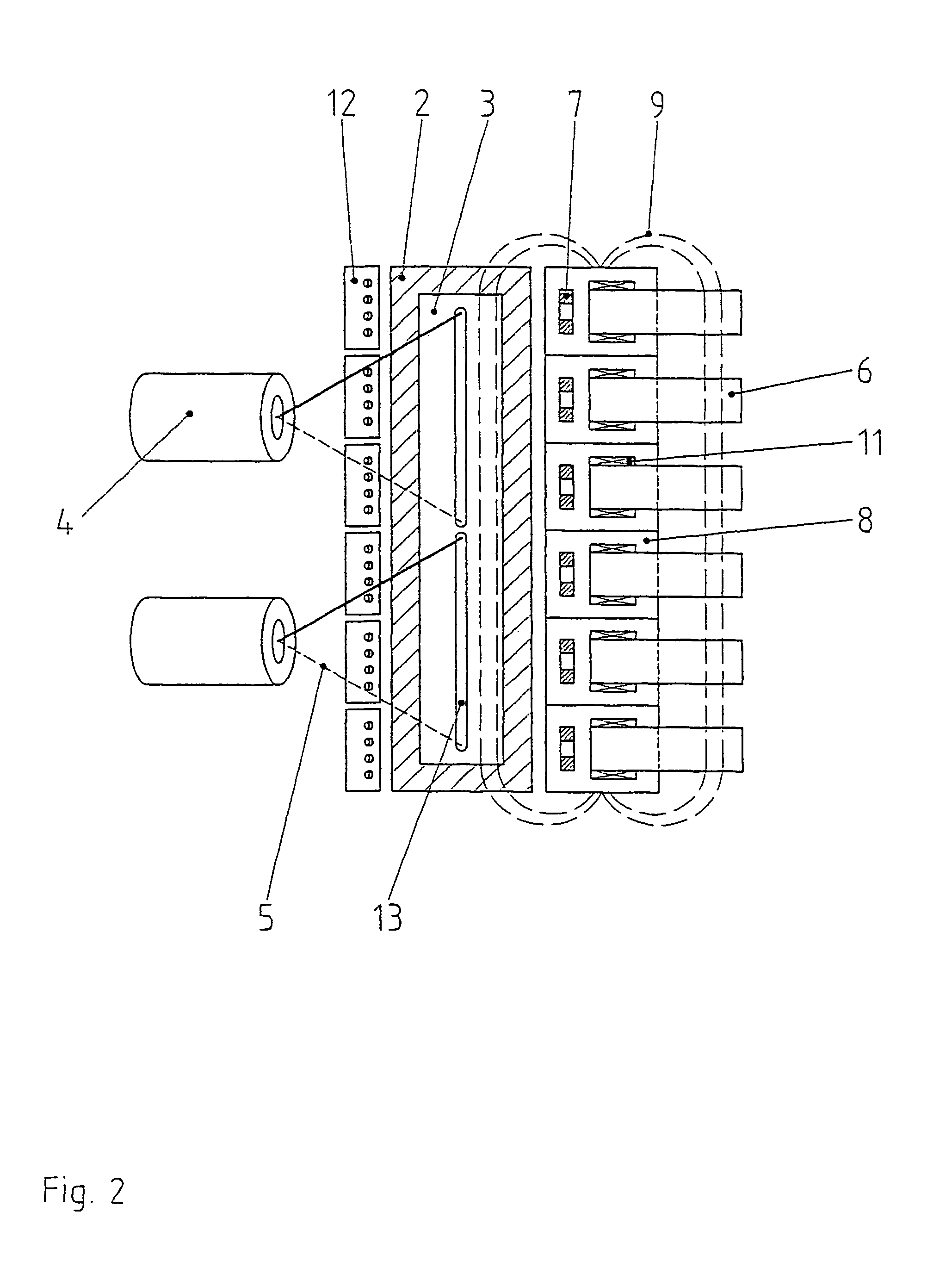
[0012]According to the invention, devices that generate magnetic fields are arranged such that a magnetic field forms whose field lines run approximately perpendicular to the movement direction and approximately parallel to the transport plane of the substrates. The arc discharge plasma sources are arranged so that their axes are aligned approximately perpendicular to the field lines of the magnetic field. The axes of the arc discharge plasma sources are preferably aligned parallel to the transport plane of the substrates. Through the magnetic field with a field direction perpendicular to the axis of the arc discharge plasma sources, the focused low-
voltage electrons of the arc discharge likewise extend perpendicular to the axis of the arc discharge plasma sources. This is due to the fact that the low-
voltage electrons with a typical energy of 10 eV are deflected in a magnetic field with a typical
field strength of 1 kA / m with a
radius of approx. 1 cm, and with this
radius as they are wrapped around the magnetic field lines running perpendicular to the plasma source and form a plasma tube. With the solutions hitherto known with the magnetic field lines running in the direction of the plasma sources axis, this effect was used to concentrate the plasma in along the plasma sources direction and thus to achieve a
high plasma density and a
large range of the plasma
stream. According to the present invention, the magnetic field lines run approximately perpendicular to the plasma sources axis so that the plasma tube likewise extends perpendicular to the axis of the plasma sources. A high uniformity of the plasma across the entire width of the substrate is thus achieved by arranging several plasma sources next to one another, even without the laborious alternating deflection.
[0015]It is particularly advantageous if an
anode is assigned to each hollow
cathode arc discharge source, which
anode is arranged either on the side of the vapor deposition zone opposite the hollow
cathode or as a ring
anode directly in front of the respective hollow
cathode. The arrangement on the opposite side of the vapor deposition zone has the
advantage that despite the alignment of the magnetic field lines perpendicular to the movement direction of the substrate, the plasma electrons are drawn through the vapor deposition zone onto the opposite anodes so that an
ionization of the entire vapor deposition zone occurs. For certain uses, e.g., for the production of gradient layers, it can be advantageous if the
plasma activation takes place only on the entry side of the substrates into the vapor deposition zone, and on the delivery side no
plasma activation or only a low
plasma activation occurs. In this case the arrangement of ring-shaped anodes directly in front of the hollow cathodes is recommended, whereby a plasma tube forms in the area of the discharge openings of the hollow cathodes perpendicular to the transport direction of the substrates and perpendicular to the axes of the hollow cathodes.
[0016]It can also be advantageous to arrange ring-shaped anodes directly in front of the hollow cathodes and to additionally assign a second anode to each ring-shaped anode, which second anode features a positive potential relative to the respective ring-shaped anode. These second anodes can be arranged on the side of the vapor deposition zone opposite the hollow cathodes as well as in the area of the
evaporator surface. With the arrangement on the side opposite the hollow cathodes, as during operation without ring anode, a uniform
ionization is achieved across the entire vapor deposition zone. With the arrangement of the second anode in the area of the evaporator surface, in a manner already known per se a potential drop in the vapor extension direction is produced which leads to an additional acceleration of ions onto the substrate and thus to improved layer properties. The second anodes can also be used in a known manner (DE 100 18 639 C 1) to admit reactive gases for the plasma activated reactive vapor deposition.
[0018]Another possibility for displacing the plasma tube from the opening of the hollow cathodes in the direction of the center of the vapor deposition zone is to surround each hollow cathode with a coaxial
magnet coil, thus generating a magnetic field parallel to the hollow cathode axis, which magnetic field bundles the low-
voltage electrons issuing from the hollow cathode in the direction of the hollow cathode axis, so that the formation of the plasma tube perpendicular to the hollow cathode axes does not occur until a greater distance from the hollow cathode openings, i.e. outside the area of the magnetic field parallel to the hollow cathode axis.
[0021]The magnetic field can also be generated through a long
magnet coil, whose length is greater than the width of the moved substrates, and whose axis is aligned perpendicular to the movement direction of the substrates and parallel to the transport plane of the substrates. It is advantageous if the long
magnet coil is provided with a ferromagnetic coil core. To influence the
plasma density distribution perpendicular to the movement direction of the substrates and / or to achieve largely identical
impact angles of the
electron beam on the evaporator surface, in the case of the
electron beam
evaporation it is expedient to adjust the distribution of direction and strength of the magnetic field across the width of the coating accordingly. This can take place through the variation of the number of windings per coil length along the coil axis. It can also take place in that the
magnet coil comprises several partial coils lined up in the axial direction, whereby the currents in the individual partial coils are adjusted differently. It has proven to be expedient to select the number of windings per coil length or the currents through the partial coils to be greater at the coil ends than in the coil center.


