Apparatus for hydrocracking a hydrocarbon feedstock

a technology of hydrocarbon oil and feedstock, which is applied in the direction of hydrocarbon oil cracking, chemical/physical/physical-chemical processes, physical/chemical process catalysts, etc., can solve the problem of reducing the function of the catalys

Active Publication Date: 2010-09-28
UOP LLC
View PDF13 Cites 13 Cited by
  • Summary
  • Abstract
  • Description
  • Claims
  • Application Information

AI Technical Summary

Benefits of technology

[0009]In one embodiment, the present invention is a process for hydrocracking a hydrocarbon feedstock to produce valuable lower boiling hydrocarbons. The hydrocarbon feedstock is hydrotreated with hydrogen to remove sulfur and nitrogen to produce hydrogen sulfide and ammonia. The resulting effluent from the hydrotreating zone contains hydrogen, hydrogen sulfide, ammonia and hydrocarbons having a reduced concentration of sulfur and nitrogen. The resulting effluent from the hydrotreating zone is directly introduced into an upper end of a hydrocracking vessel maintained at essentially the same pressure as the hydrotreating zone to produce a generally upwardly flowing gaseous stream comprising hydrogen sulfide, ammonia and hydrogen, and a generally downwardly flowing liquid stream comprising hydrotreated hydrocarbons. The upwardly flowing gaseous stream contains essentially all of the vapor from the hydrotreating zone and is removed from the top of the hydrocracking vessel. A liquid hydrocarbon seal prevents the flow of the vapor to the lower portion of the hydrocracking vessel which holds the hydrocracking catalyst. The downwardly flowing liquid stream comprising hydrotreated hydrocarbons is admixed with a hydrogen rich gaseous stream and the resulting admixture is reacted in a hydrocracking zone containing hydrocracking catalyst. The resulting effluent from the hydrocracking zone is recovered to provide hydrocracked hydrocarbons.

Problems solved by technology

The use of the liquid hydrocarbon seal prevents the hydrogen sulfide and ammonia from contacting the hydrocracking catalyst which has a deleterious effect on the function of the catalyst.

Method used


Image

  • Apparatus for hydrocracking a hydrocarbon feedstock
  • Apparatus for hydrocracking a hydrocarbon feedstock

Examples


Embodiment Construction

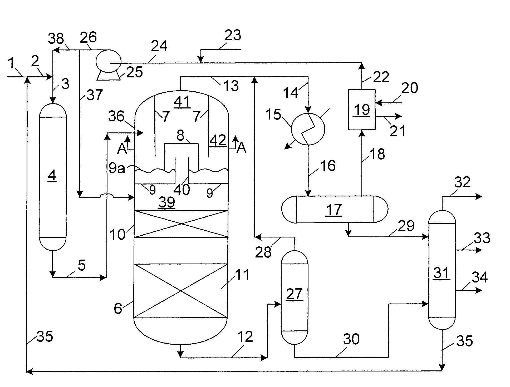
[0015]The present invention is an integrated process for the hydrotreating and hydrocracking of heavy distillate hydrocarbon streams. Preferred feedstocks to the hydrotreating reaction zone include distillate hydrocarbons boiling at a temperature greater than about 371° C. (700° F.). A suitable feedstock is a typical vacuum gas oil normally boiling in the range from about 315° C. (600° F.) to about 565° C. (1050° F.). Distillate hydrocarbon feedstocks are most often recovered from crude oil distillation. However, distillate hydrocarbons may be utilized from any convenient source such as tar sand extract and gas to liquids for example. Furthermore, the distillate hydrocarbon feedstocks may contain from about 0.1 to about 4 weight percent sulfur or from about 0.05 to about 1 weight percent nitrogen.

[0016]In one embodiment of the present invention, a selected heavy distillate hydrocarbon feedstock is introduced into a hydrotreating reaction zone together with a hydrogen-rich gaseous st...


PUM

PropertyMeasurementUnit
boiling pointaaaaaaaaaa
temperatureaaaaaaaaaa
weight percentaaaaaaaaaa

Abstract

A hydrocracking process and apparatus wherein the feedstock is hydrotreated and the liquid and gaseous effluent from the hydrotreater is directly introduced into the upper end of a hydrocracking vessel which provides a liquid seal to prevent the passage of the gaseous stream containing hydrogen sulfide and ammonia from the hydrotreater to enter the hydrocracking zone containing hydrocracking catalyst. Fresh hydrogen is then introduced into the hydrocracking zone.

Description

FIELD OF THE INVENTION[0001]The field of art to which this invention pertains is the catalytic conversion of a hydrocarbon feedstock to produce useful lower boiling hydrocarbon products by hydrodesulfurization and hydrocracking. An apparatus for hydrocracking a hydrocarbon feedstock is also disclosed.BACKGROUND OF THE INVENTION[0002]Petroleum refiners produce desirable products such as turbine fuel, diesel fuel and other products known as middle distillates, as well as lower boiling hydrocarbonaceous liquids, such as naphtha and gasoline, by hydrocracking a hydrocarbon feedstock derived from crude oil or heavy fractions thereof. Feedstocks most often subjected to hydrocracking are gas oils and heavy gas oils recovered from crude oil by fractionation. A typical heavy gas oil comprises a substantial portion of hydrocarbon components boiling above about 371° C. (700° F.), usually at least about 50% by weight boiling above 371° C. (700° F.). A typical vacuum gas oil normally has a boili...

Claims


Application Information

Patent Timeline
Patent Type & Authority Patents(United States)
IPC IPC(8): B01J8/02C10G47/00
CPCB01J8/0453B01J8/0492C10G47/00B01J2208/00274B01J2208/025
Inventor HOEHN, RICHARD K.THAKKAR, VASANT P.MURTY, VEDULA K.KOCHER-COWAN, DOUGLAS W.ANDERSON, JENNIFER L.
Owner UOP LLC
Why Eureka
Try Eureka