
Process for manufacturing dimethyl carbonate

a technology of dimethyl carbonate and dimethyl carbonate, which is applied in the field of process for manufacturing dimethyl carbonate, can solve the problems of difficult to achieve cost-efficient recycling of byproduct stream, inconsistency of chemical and chemical concentration in byproduct line, and non-phosgene process

Inactive Publication Date: 2010-09-28
SABIC GLOBAL TECH BV
View PDF48 Cites 5 Cited by
  • Summary
  • Abstract
  • Description
  • Claims
  • Application Information

AI Technical Summary

Benefits of technology

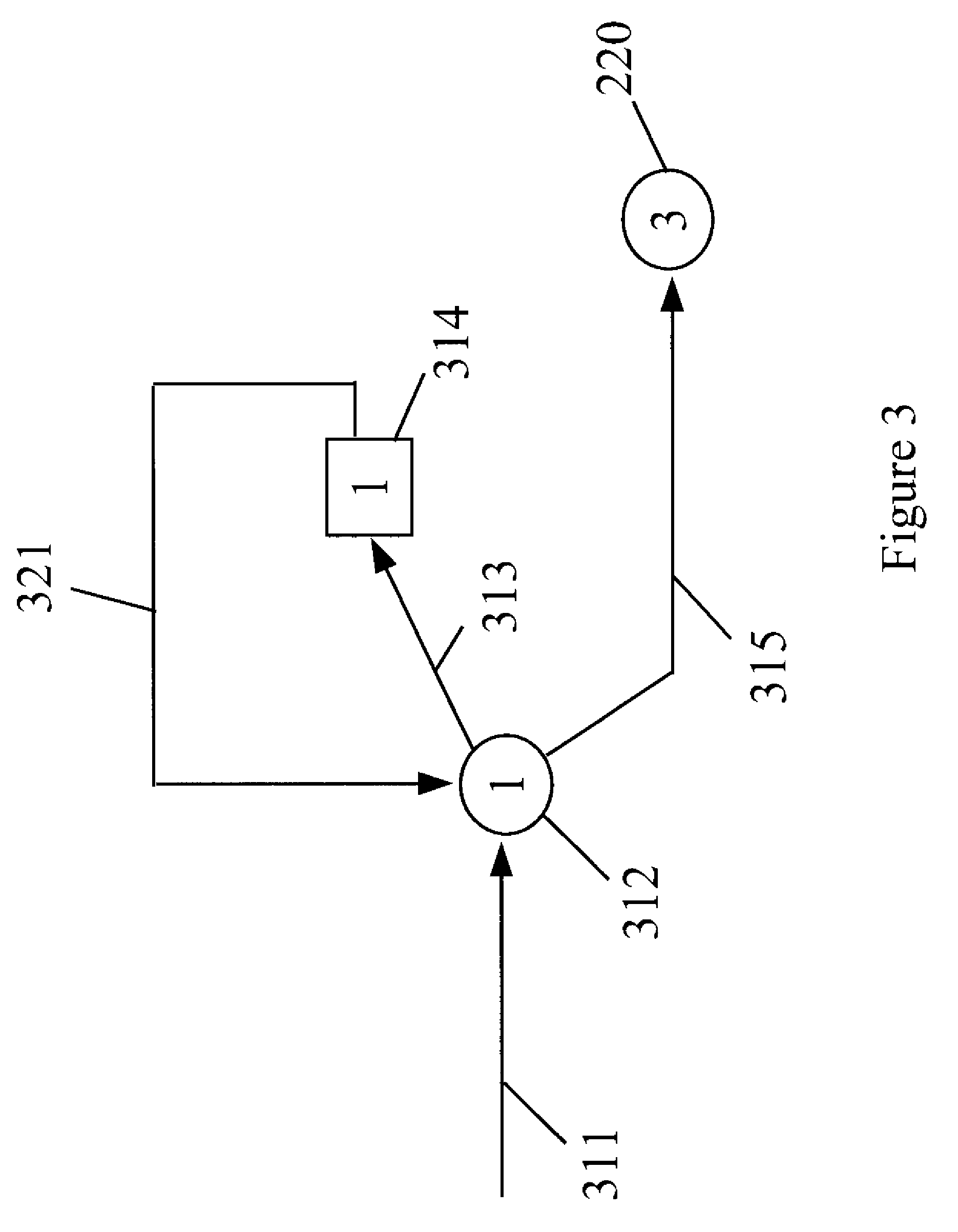
The present invention provides a method for recycling a byproduct line from a diaryl carbonate production plant and using residual alkanol to form or reform dialkyl carbonate. The method involves separating the byproduct stream to produce two dialkyl carbonate streams, which are then combined to form a combined dialkyl carbonate stream. This allows for the efficient recycling of the byproduct line and the residual alkanol can be used in a later diaryl carbonate formation reaction. The technical effect of this invention is the improved efficiency and economics of diaryl carbonate production.

Problems solved by technology

The toxicity of phosgene, however, prompted the development of a non-phosgene process.
Cost-efficient recycling of the byproduct stream has however proven to be difficult to achieve.
Process instabilities occurring in the diaryl carbonate production facility lead to inconsistent chemicals and chemical concentrations in the byproduct line.
Furthermore, a water leak in the diaryl carbonate production facility may cause separation problems leading to an increase in byproducts and residual reaction components in the byproduct line.
Diaryl carbonate formation reaction byproducts or residual reaction components including aromatic alcohol (e.g. phenol) and its aromatic ether byproduct (e.g. anisole) can lead to reactivity or separation problems or to the formation of chlorinated aromatics (e.g. di- and tri-chlorophenols and chloroanisols) which can degrade in separation equipment of a dialkyl carbonate plant and cause fouling in piping and process equipment.
When this happens chlorophenols and chloroanisoles can be formed in the dialkyl carbonate reactors and can thermally decompose in later stages of the process forming a coke-type residue that can clog transfer lines, reactors, separation equipment, and heat transfer equipment.
This has proven to be cost inefficient in that significant additional labor, energy, and equipment costs would be required to recycle the byproduct line.
Due to this cost inefficiency and no matter what the good intentions of the company toward the environment are, the byproduct line and its contents are often discarded.

Method used


Image

  • Process for manufacturing dimethyl carbonate
  • Process for manufacturing dimethyl carbonate
  • Process for manufacturing dimethyl carbonate

Examples


examples

[0079]Having described the invention in detail, the following examples are provided. The examples should not be considered as limiting the scope of the invention, but merely as illustrative and representative thereof.

Illustration 1:

[0080]A computer simulation using Aspen Simulation software was run to determine the product stream component concentration on streams from an azeotrope distillation column having 60 theoretical trays. Six runs were performed using six different feed stream compositions from a proposed diaryl carbonate production facility. These feed stream configurations are indicated in Table 1. The azeotrope distillation column was set to run throughout the six runs according to the following additional parameters:[0081]Top Product Stream: 28 wt % (maximum) dimethyl carbonate (DMC) and 1 ppm (maximum) aromatic alcohol.[0082]Top Condenser Reflux Ratio (L / D): 1.35.[0083]First feed stream: 53,956 Kg / hr (50.96 wt % MeOH, 41.40 wt % DMC, 3.78 wt % water, the balance include...

experiment 1

[0090]A mixture comprising 16.5 ml water, 83.5 ml DMC, and 0.015 ml methanol was prepared and introduced to a flask at 60° C. Also introduced to the flask was 1 gr of phenol and 1 gr of anisole. The flask was sealed and the mixture was stirred for five minutes and cooled to room temperature. The mixture separated into two phases (aqueous and organic) and component concentrations of each phase was analyzed by gas chromatography (GC) and are reported in Tables 3 and 4.

experiment 2

[0091]A mixture comprising 16.5 ml water, 83.5 ml DMC, 0.015 ml methanol was prepared and introduced to a flask at 60° C. Also introduced to the flask was 5 gr of phenol and 5 gr of anisole. The flask was sealed and the mixture was stirred for five minutes and cooled to room temperature. The mixture separated into two phases (aqueous and organic) and component concentrations of each phase was analyzed by GC and are reported in Tables 3 and 4.

[0092]Experiments 1 and 2 demonstrate that anisole and phenol impurities remain largely in the organic phase while only small amounts are contained in the aqueous phase. Furthermore, the presence of anisole and / or phenol up to 5 wt % in the bottom stream from azeotrope column in a DMC plant will not impair water separation in the decanter / water separator downstream therefrom.

[0093]

TABLE 3Organic Phase(% weight on water free basis)MethanolDMCAnisolePhenolExperiment 10.0197.591.291.11Experiment 20.0188.236.095.67

[0094]

TABLE 4Aqueous Phase(% weight...


PUM

PropertyMeasurementUnit
pressureaaaaaaaaaa
pressureaaaaaaaaaa
temperatureaaaaaaaaaa

Abstract

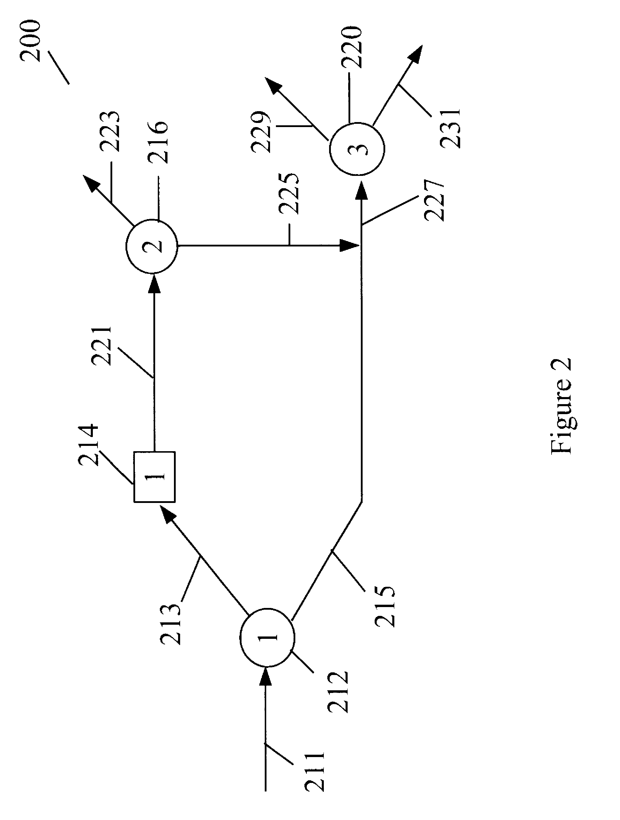
A method of forming a dialkyl carbonate stream, includes obtaining a byproduct stream from a diaryl carbonate formation reaction that has alkanol, residual dialkyl carbonate, and residual aromatic compound. This byproduct stream is introduced to a distillation column to produce an alkanol tops stream and a first dialkyl carbonate bottoms stream. The alkanol tops stream is reacted with oxygen, carbon monoxide, and catalyst to form a second dialkyl carbonate stream that is introduced to the distillation column. The alkanol tops stream from the column contains alkanol, dialkyl carbonate, and less than 20 ppm aromatic compound. The first dialkyl carbonate bottoms stream from the column contains dialkyl carbonate, water, aromatic compound, and less than 2,000 ppm alkanol and is introduced to a water separation device to produce a product dialkyl carbonate stream and a water stream.

Description

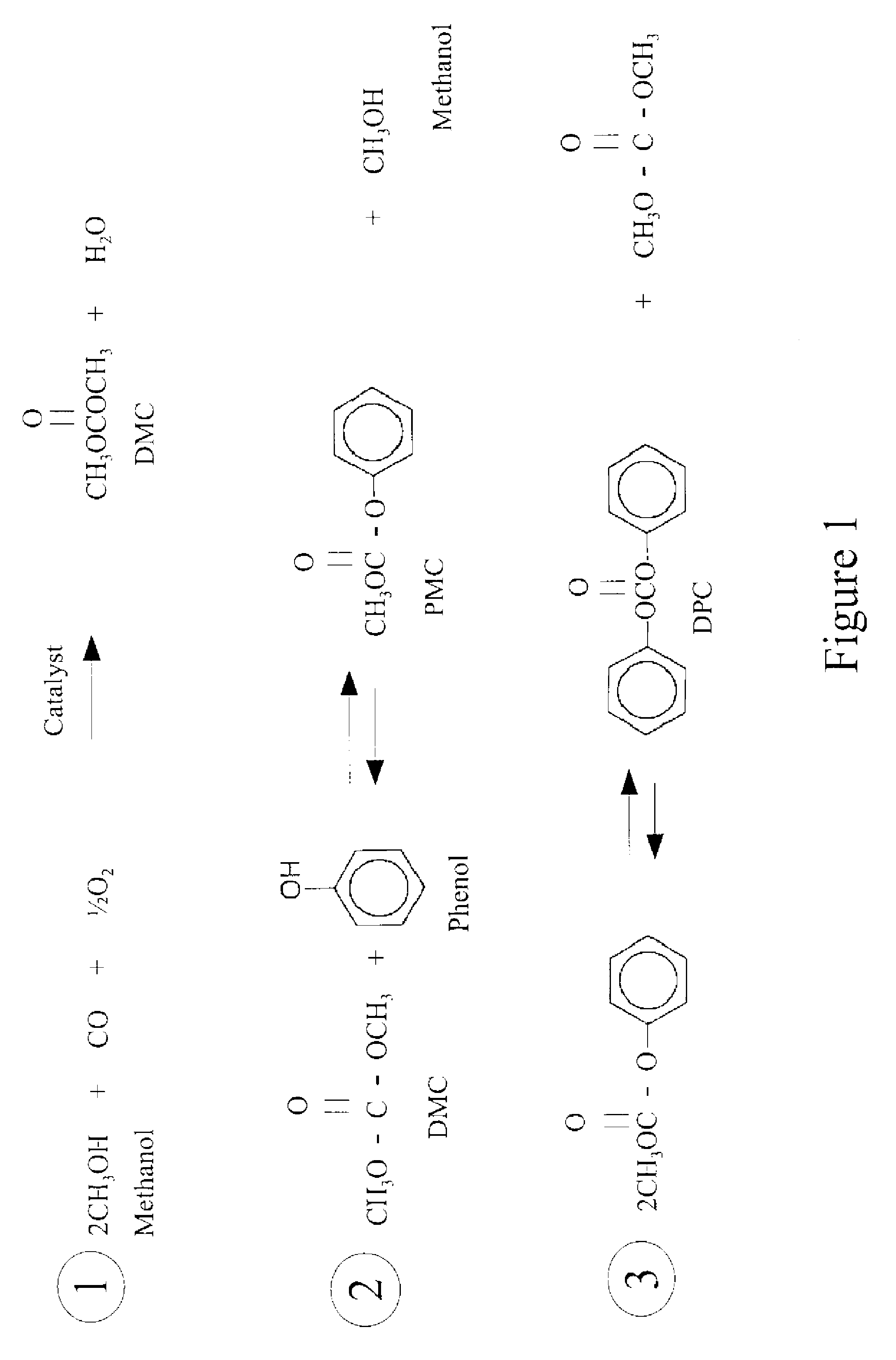
CROSS-REFERENCE TO RELATED APPLICATIONS[0001]The present application claims priority from and is a non-provisional application of U.S. Provisional Patent Application Ser. No. 60 / 890,277 filed on Feb. 16, 2007, which is incorporated herein by reference for all purposes.BACKGROUND OF THE INVENTION[0002]Diaryl carbonates, such as diphenyl carbonate, are an important reactant in the production of polycarbonate resins. As the uses to which polycarbonates are put have increased, the safe and efficient production of diaryl carbonates has become of greater significance. Early processes for the production of diaryl carbonates utilized phosgene as a reagent. The toxicity of phosgene, however, prompted the development of a non-phosgene process. The non-phosgene process is well-known in the art and is described in U.S. patent application Ser. Nos. 4,410,464, 5,344,954, 6,784,277, 7,141,641, and 7,288,668, which are incorporated herein by reference.[0003]As shown schematically in FIG. 1, the non...

Claims


Application Information

Patent Timeline
Patent Type & Authority Patents(United States)
IPC IPC(8): C07C69/96
CPCC07C68/005C07C68/06C07C69/96C07C68/01
Inventor VIC FERNANDEZ, IGNACIO
Owner SABIC GLOBAL TECH BV
Learn More