[0008]Therefore the object of the present invention is to provide an apparatus of the kind set forth in the opening part of this specification and a method of the kind set forth in the opening part of this specification, with which the disadvantages of the state of the art are reduced. In particular, the invention aims to reduce deposits in the combustion chamber-side region of the combustion chamber window.
[0011]It is possible with the apparatus according to the invention to cause a fluid to flow continuously on to the combustion chamber window and more specifically at the interface of the combustion chamber window, at the combustion chamber side, or between the focal point and the combustion chamber window so that deposits formed by combustion of the fuel / air mixture cannot be deposited at the combustion chamber window. In that way, the combustion chamber window is kept free of deposits at the combustion chamber side and the laser can be operated with a lower level of power as there is no interference absorption due to deposits on the combustion chamber window. There is also no need for the laser to be operated at a
power level which burns free or removes again the deposits on the combustion chamber window. Overall, that measure greatly increases the service life of the entire apparatus. The method according to the invention makes it possible for the fluid to be caused to flow on to the combustion chamber window (more specifically on to the interface thereof, that is at the combustion chamber side) or the region between the combustion chamber window and the focal point of the laser light. It is desirably provided that the fluid involves no or only minimal interactions with the laser light so that in the preferred case the fluid is a gas, particularly preferably air or an
inert gas. In the present case it is sufficient as an
inert gas if the interaction with the laser light does not result in a
chemical reaction. With a fuel / air mixture in the correct mixture ratio, the interaction leads to an ignition effect so that such a fluid would be unsuitable while air which in the conventional sense cannot be considered to be an
inert gas by virtue of the
high oxygen content can in the present case certainly be an
inert gas as air generally is not caused to react with laser light alone or is caused to react only to a slight extent which does not cause any problem. Overall that depends on the laser light aspect, for example the levels of
light intensity, wavelengths and pulse durations, so that the average man skilled in the art is in a position to select a suitable fluid. By way of example, CO2,
nitrogen,
noble gas or mixtures thereof would be considered as the
inert gas. A low degree of light absorption by the fluid can be tolerated.
[0012]By virtue of the high pressures in the combustion chamber, it is preferably provided that the fluid—preferably gas—is caused to flow thereinto under a pressure which is above the induction pressure or filling pressure of the combustion chamber. In the ideal case, the increased pressure is at least 1 bar above the induction pressure. Such a choice for the pressure makes it possible to counteract the high pressures in the combustion chamber so that the
diffusion of the combustion residues towards the combustion chamber window can be reduced to a high degree.
[0014]It can further be provided that the fluid feed device has a valve for fluid metering. The amount of fluid can be optimally metered by a valve. In the situation where the valve is in the form of a
check valve, a reverse flow of gases out of the combustion chamber is prevented. In the situation where the valve is in the form of a metering valve, the amount and the pressure of the fluid can be regulated in the optimum fashion.
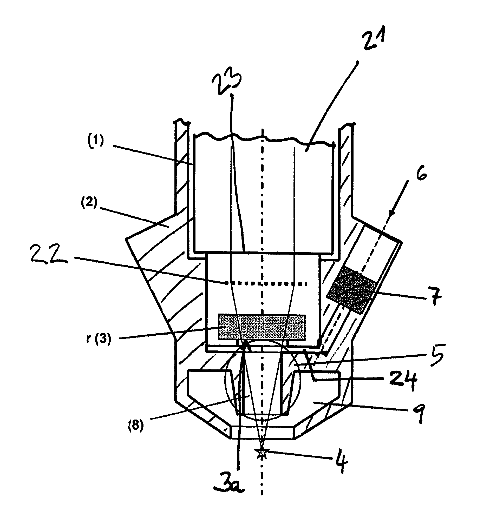
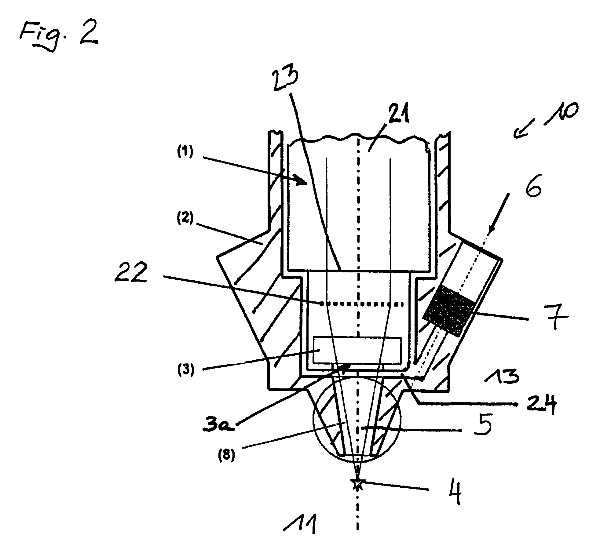
[0015]It is particularly preferably provided that the apparatus has a prechamber arranged in a region between the combustion chamber window and the focal point of the laser light. The region into which the fluid is caused to flow between the combustion chamber window and the focal point can be spatially optimally regulated by that measure. In addition, the gas flow out of the combustion chamber towards the combustion chamber window is reduced by virtue of the spatial delimitation. In that respect, it is advantageously provided that the prechamber is arranged between the combustion chamber window and the focal point of the laser light, whereby the region through which gas fluid flows is clearly defined. It has been found that such a prechamber reduces the amount of fluid required and optionally the feed of fluid can also be interrupted at times in operation.
[0016]In an embodiment, it is provided that the apparatus has a further prechamber which encloses at least the region of the first prechamber. In that respect it is possible once again to distinguish between two advantageous variants. In the first case, the second prechamber serves to even better shield the first prechamber from the gas flow out of the combustion chamber and to reduce a turbulent flow. In the second case, a fluid can be introduced into the second prechamber. In that case, in a further variant, it can be provided that the fluid which can be introduced into the second prechamber is an air / fuel mixture which preferably has a lower
lambda λ (ratio of air to fuel) than the
lambda λ in the combustion chamber. In that way, the second prechamber region with a higher fuel content can be used for preignition which then initiates actual ignition of the lean mixture in the combustion chamber. In that respect, the focal point of the laser light is arranged in the
edge region or in the
central region of the second prechamber.

