Method and apparatus for an improved mass spectrometer

a mass spectrometer and mass spectrometer technology, applied in the direction of dispersed particle separation, instruments, separation processes, etc., can solve the problem that macromolecular ions do not give a strong signal response from conventional ionizing detectors, and achieve the effects of improving mass accuracy, detection limits and sensitivity, and improving resolution

Inactive Publication Date: 2010-10-05
CARNEGIE MELLON UNIV
View PDF15 Cites 47 Cited by
  • Summary
  • Abstract
  • Description
  • Claims
  • Application Information

AI Technical Summary

Benefits of technology

[0011]This invention teaches improved methods and apparatuses for selective mass analysis of ions by measuring the photons emitted from ions in an “optical” mass spectrometer. Laser induced fluorescence (LIF) or light scattering are two processes that could be used to make such an optical measurement. The invention should improve resolution, mass accuracy, detection limits and sensitivity with efficient photon excitation and simultaneous measurement of the frequency and intensity of ion fluorescence from an ensemble of trapped ions. The secular frequencies of all the stored fluorescing ions can be measured at once by detecting the frequency of the photons emitted after inhomogeneous laser excitation of the trapped ion volume or individually by moving the select ion or ions into the measurement region. Additionally, unique fluorescent tag molecules with specific excitation and emission frequencies may be chosen. Efficient photon excitation can be accomplished by using lasers, large excitation volumes with a large cross-section and long absorption path lengths, mirrors and strong fluorescent tag molecules. Fluorescent tag molecules may not be needed if the ion already fluoresces. Efficient photon detection can be accomplished by using an optical trap with light pipes, reflective or transparent electrodes and focusing light optics so that the maximum number of photons can be detected and measured. The detection scheme allows the same set of ions to be mass analyzed repetitively and without ion loss. That is, ions do not require ejection from the device for LIF or light scattering mass analysis and an array of “optical traps” could be used to extend the analysis

Problems solved by technology

For example, macromolecular ions do not give a strong

Method used


Image

  • Method and apparatus for an improved mass spectrometer
  • Method and apparatus for an improved mass spectrometer
  • Method and apparatus for an improved mass spectrometer

Examples


Embodiment Construction

Optical Trap

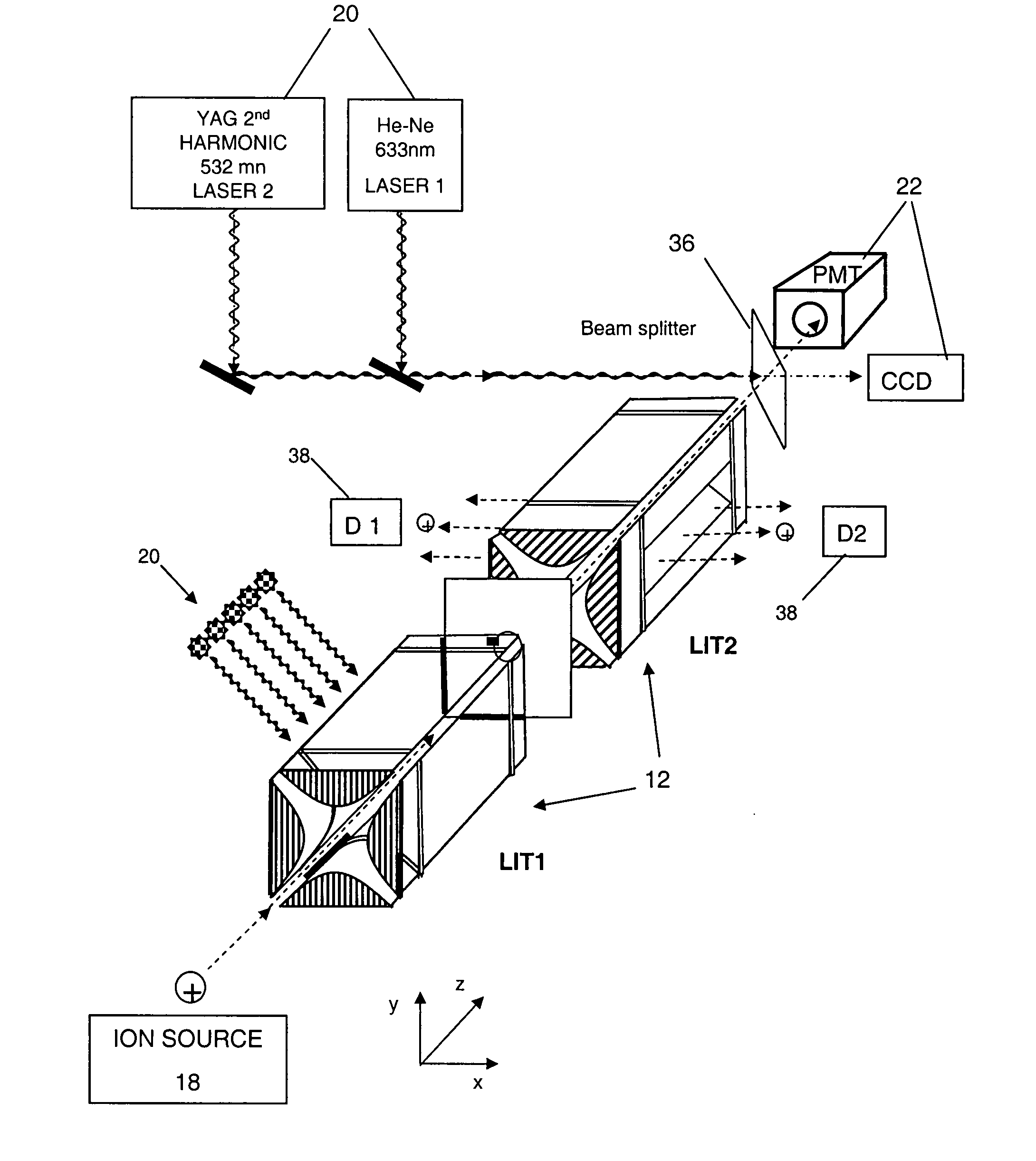
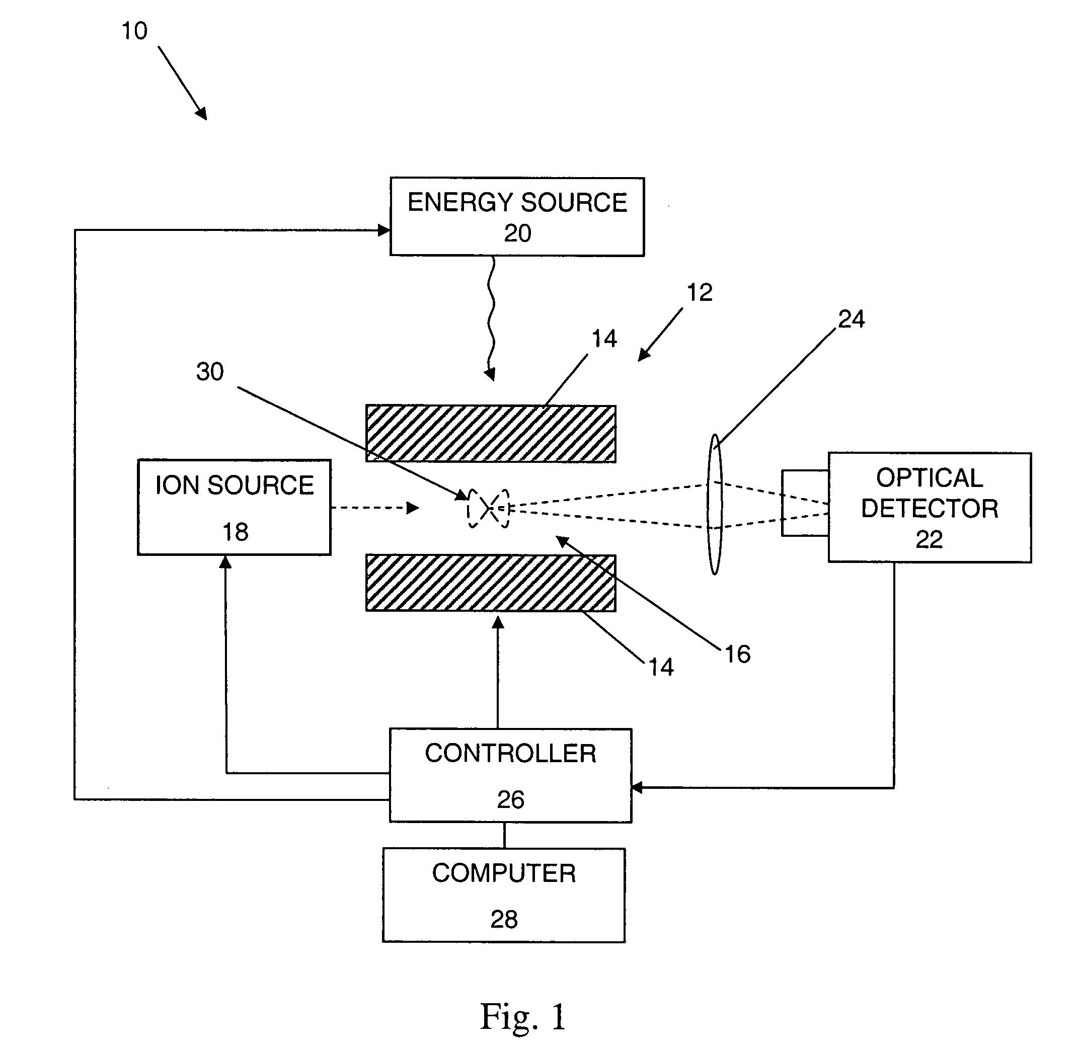
[0062]FIG. 1 illustrates one embodiment of an apparatus 10 according to the present invention. The apparatus 10 includes an ion trap 12, a plurality of electrodes 14 defining a trapping chamber 16, an ion source 18, an energy source 20, an optical detector 22, a controller 26, and a computer 28. Ions from the ion source 18 are injected into the ion trap 12, where they are trapped or contained. The energy source 20 excites the ions in the ion trap 12 and the optical detector 22 detects photons emitted from the ions in the trap 12. This embodiment also illustrates exemplary trajectories 30 of ions within the trapping chamber 16.

[0063]The ion trap 12 will generally be described as a linear ion trap (“LIT”), although the present invention may be used with other forms of ion traps and is not limited to the specific embodiments described herein. For example, the ion trap 12 may be other forms of ion traps such as, for example, a three-dimensional or two-dimensional quadrupole ...


PUM


Abstract

An apparatus including a plurality of electrodes defining a trapping chamber of an ion trap, wherein at least one of the electrodes is a transparent electrode having at least a portion that is both optically transparent and electrically conductive; a controller connected to the plurality of electrodes, wherein the controller includes a memory containing computer readable instructions which, when executed, cause the controller to send control signals to the plurality of electrodes so that: the plurality of electrodes produce and maintain a trapping field in the trapping chamber, and the plurality of electrodes change the trapping field so that ions of a predetermined mass in the trapping chamber are selectively moved; and an optical detector oriented so that the portion of the transparent electrode that is both optically transparent and electrically conductive is between the optical detector and the trapping chamber.

Description

CROSS-REFERENCE TO RELATED APPLICATIONS[0001]This application claims priority from U.S. Provisional Patent Application No. 60 / 846,020, filed Sep. 20, 2006, which is incorporated herein by reference.STATEMENT REGARDING FEDERALLY-SPONSORED RESEARCH AND DEVELOPMENT[0002]Not Applicable.FIELD OF THE INVENTION[0003]The present invention is directed generally to a method and apparatus for an improved mass spectrometer.BACKGROUND OF THE INVENTION[0004]Many different mass analyzers are used in the field of mass spectrometry. The most common mass analyzers include ion-cyclotron resonance (ICR) or Fourier transform mass spectrometer (“FTMS”), ion traps, quadrupole, time-of-flight, orbitraps and magnetic sector instruments. All of the commercial versions of these instruments detect the ions by using an ionizing particle detector or by measuring an electrical image current as done when using the Fourier transform technique for FTMS and the orbitrap. Although there has been experimental work usin...

Claims


Application Information

Patent Timeline
IPC IPC(8): H01J49/00
CPCH01J49/422H01J49/4255G01N21/53G01N21/6428
Inventor BIER, MARK E.
Owner CARNEGIE MELLON UNIV
Why Eureka
Try Eureka