
Heavy oil recovery with fluid water and carbon dioxide

a technology of fluid water and carbon dioxide, which is applied in the direction of fluid removal, earth-moving drilling, borehole/well accessories, etc., can solve the problems of increasing the cost of extraction, and difficulty in discovering conventional oil reserves, so as to improve the extraction efficiency and improve the extraction efficiency. , the effect of increasing co2

Active Publication Date: 2010-10-19
VAST HLDG LLC
View PDF20 Cites 74 Cited by
  • Summary
  • Abstract
  • Description
  • Claims
  • Application Information

AI Technical Summary

Benefits of technology

"The present invention provides improvements to the process of extracting heavy hydrocarbons from geological formations or mined materials. The invention involves delivering a hot process fluid containing combustion gases, carbon dioxide, and water to the heavy hydrocarbon bearing material for recovery of at least a portion of the heavy hydrocarbon. The hot process fluid is generated by combusting a mixture of fuel, oxidant, and water in a wet combustion process. The recycled water, carbon dioxide, and hydrocarbon vapor can be used to control the outlet fluid temperature of the combustor. The use of the hot process fluid has the potential to improve the efficiency of heat transfer and reduce the amount of heat required for a given amount of heavy hydrocarbon extraction. The method can generate hot process fluids with enhanced water and carbon dioxide, and greater flexibility in controlling the composition of the hot process fluid. The fuel used in the process can be natural gas, coke, coal, or diesel, and the process is tolerant of contaminants in the fuel. The method can also improve heavy hydrocarbon extraction efficiency by enhancing CO2 in the hot process fluid."

Problems solved by technology

However, discovery of conventional oil reserves has been declining since the mid 1960s.
Such alternative hydrocarbon resources have been more difficult, complex and expensive to recover and process than conventional petroleum resources.
However, most bitumen in place is not economically recoverable using conventional surface extraction techniques.
However, the energy used to extract heavy hydrocarbons (especially oil shale) using conventional techniques may exceed the energy recovered (i.e. EROEI <1.0).
However CO2 is often difficult to obtain near heavy hydrocarbon resources.
Long expensive pipelines are typically used to deliver CO2.
The market for elemental sulfur is currently saturated.
Conventional turbines using the “Simple cycle” or “Brayton Cycle” typically produces high lateral and axial temperature differentials which may lead to NOx formation at peak and high temperature locations regions in the combustor.

Method used


Image

  • Heavy oil recovery with fluid water and carbon dioxide
  • Heavy oil recovery with fluid water and carbon dioxide
  • Heavy oil recovery with fluid water and carbon dioxide

Examples


example 1

100° C. Atmospheric VASTgas from Natural Gas Fuel (Water / Fuel=W / F=ω=10.6)

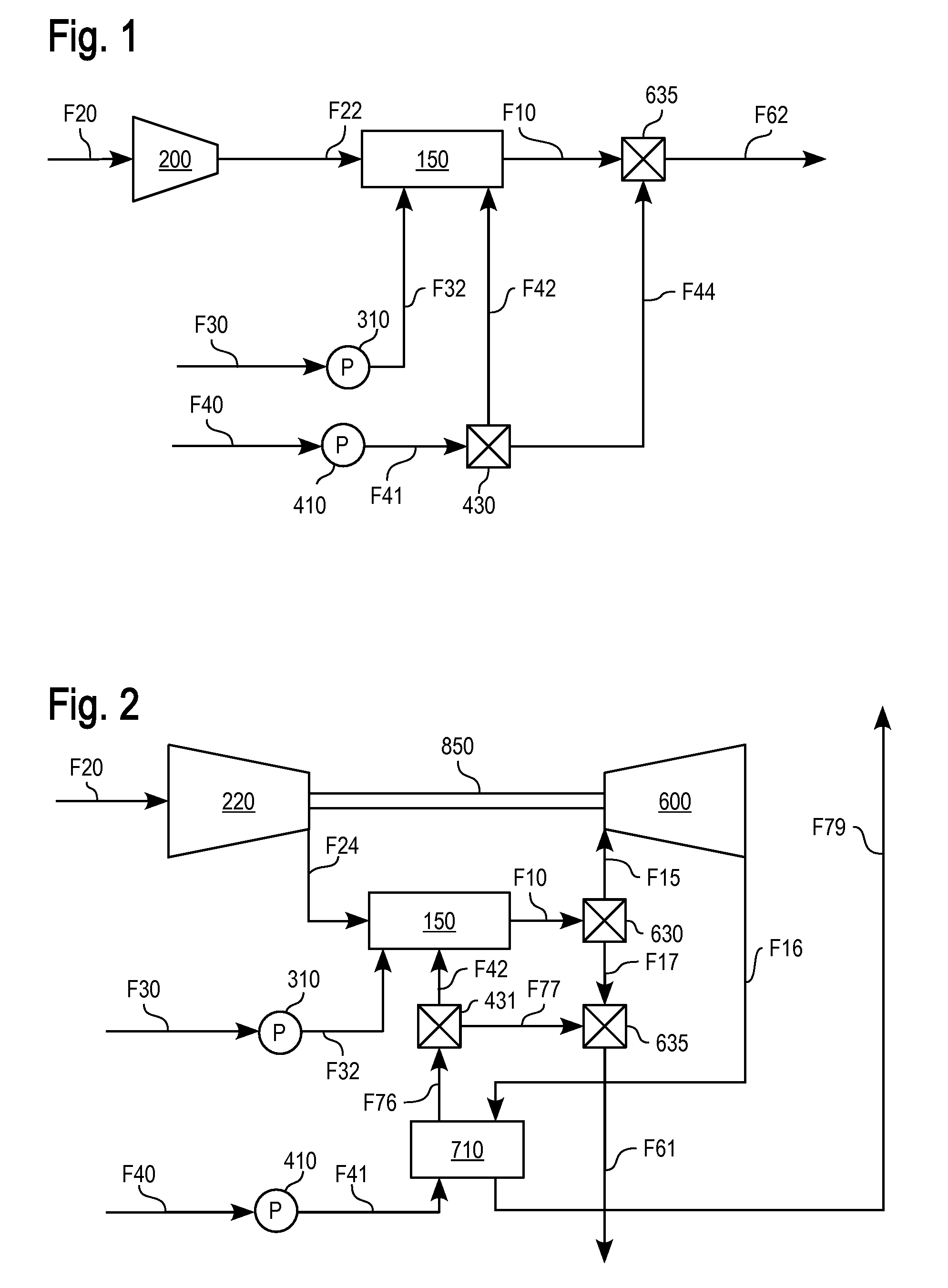
[0092]Referring to FIG. 1, in one embodiment, a fuel fluid comprising fuel F30 is pressurized by a pressurizer, pump, blower, or compressor 310 which delivers a pressurized fuel fluid F32 to a VAST combustor, or thermogenerator 150. An oxidant fluid comprising an oxidant F20 is pressurized by a pressurizer, pump, blower, or compressor 200 which delivers a pressurized oxidant fluid F22 to the combustor 150. oxidant and fuel are combusted to form products of combustion. Diluent fluid F40 is pressurized by a pressurizer, pump, blower, or compressor 410 to form pressurized diluent fluid F41.

[0093]A portion of diluent fluid F41 may be distributed by splitter distributor 430 to deliver combustor diluent fluid F42 upstream of the outlet of combustor 150 to form VASTgas or process fluid F10 comprising products of combustion and vaporized thermal diluent. Another portion F44 of diluent fluid F41 may be mixed with the VA...

example 2

1 atm VAST Cycle Burning Coke Fuel (Water / Fuel =ω=7.1)

[0107]In another configuration C1C, an atmospheric VAST cycle burner was modeled burning coke with combustion gases diluted to a temperature of 482° C. (900° F.) with a small excess air as oxidant fluid. Coke composition: 79.7% C, 4.47% S, 2.3% H, 10.6% H2O, 0.27% ash; 5% excess air. i.e. Λ=1.05). Table 1 shows the mole fraction compositions of input gases / fuel and VASTgas outputs. The input flow rates of fuel, air and water were 0.45 kg / s, 5.32 kg / s, and 3.20 kg / s respectively, giving a W / F ω of 7.1. The input temperatures were 15° C. for air and water, and 25° C. for fuel.

[0108]The energetic fluid (VASTgas) temperature for this example is 100° C. Additional water at 1.86 kg / s is added to the combustion gases to reduce their temperature from the 482.2° C. combustor outlet temperature to 100° C. (total water flow=5.07 kg / s). Delivering VASTgas at 100° C. provides the maximum steam in the VASTgas without condensation.

[0109]The CO2...

example 3

Diverted VAST Cycle Gas Turbine Combustion Gases

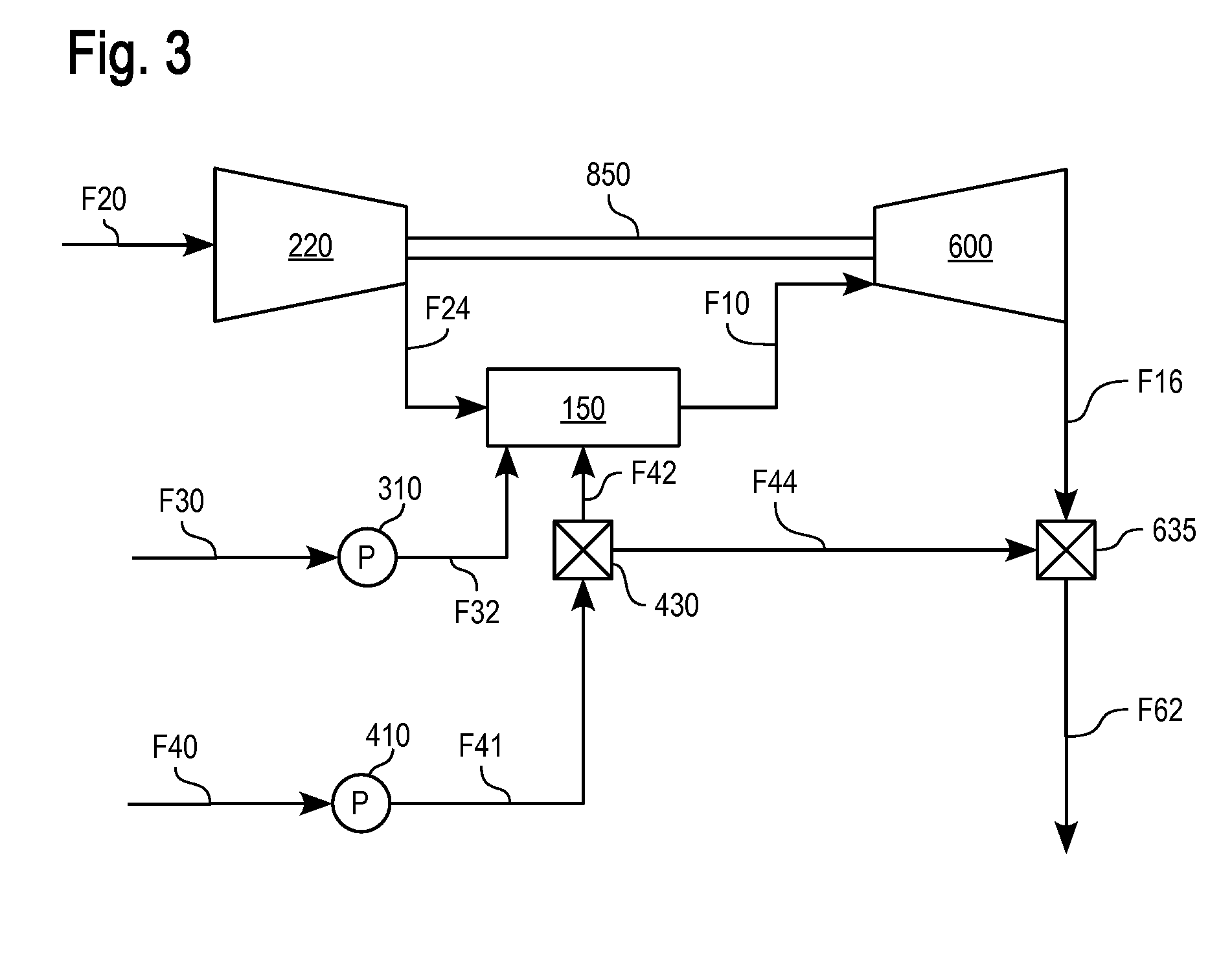
[0113]Gas turbines are highly efficient means to produce both electricity and mechanical energy at high specific power levels from various fuels. The use of high water (liquid water or steam) injection levels to increase the specific power of such systems is well known in the art, e.g., U.S. patent application Ser. No. 10 / 763,057 (Hagen et al.). Using water allows higher fuel injection levels for a given input fluid flow (water and air). This is due to the higher specific heat of water as compared to air and the corresponding ability of water to provide greater cooling for a given mass flow of fuel being combusted.

[0114]

TABLE 1VAST Thermogenerator wet combustion vs dry combustion.OUTPUT GASESINPUT GASES / FUELVASTVASTVASTVASTDryDryCoke FuelNG FuelAir v %Gas v %Gas v %Gas v %Gas v %CombustionCombustionAtom orv % atv % atat 15° C.at 482° C.at 100° C.at 482° C.at 100° C.v % atv % atMolecule25° C.25° C.RH 60%(coke)(coke)(NG)(NG)1035° C. (NG)...


PUM


Abstract

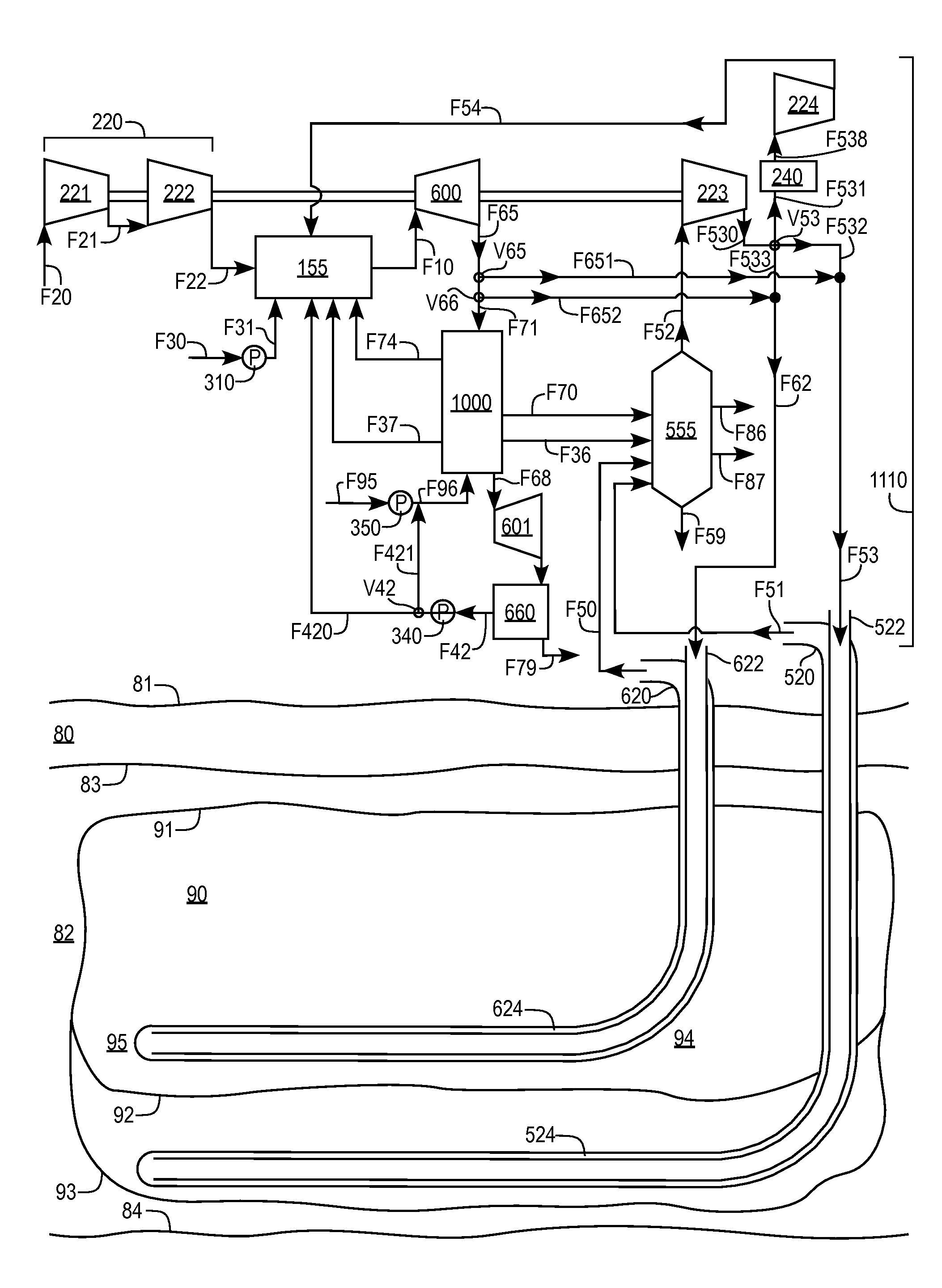
Diluted wet combustion forms a hot process fluid or VASTgas including carbon dioxide (CO2) and fluid water which is delivered to geologic formations and / or to surface mined materials to reduce the viscosity and / or increase hydrocarbon extraction. High water and / or CO2 content is achieved by reducing non-aqueous diluent and / or adding or recycling CO2. Power recovered from expanding the VASTgas may be used to pressurize the VASTgas for delivery by partial expansion through a Direct VAST cycle, and / or by diverting compressed oxidant through a parallel thermogenerator in a Diverted VAST cycle. Pressurized VASTgas may be injected into a well within the hydrocarbon formation or with mined material into a heavy hydrocarbon separator vessel to heat, mobilize, solubilize and / or extract heavy hydrocarbons. Light hydrocarbons may be mixed in with the hot process fluid to enhance hydrocarbon mobilization and recovery. Microwaves may further heat the VASTgas and / or hydrocarbon. Sulfur oxidation, calcining limestone and / or recycling may increase CO2. Oxygen enrichment may increase the specific power. VASTgas may be delivered through and back injection wells and / or production wells, and / or between sequential injection wells in alternating and / or paired zigzag formations with multiple wells per VAST combined heat and power recovery system.

Description

CROSS-REFERENCE TO RELATED APPLICATIONS[0001]This application claims priority under 35 U.S.C. §119(e) of U.S. Provisional Patent Application No. 60 / 994,196, filed 18 Sep. 2007, entitled HOT FLUID RECOVERY OF HEAVY OIL WITH ENHANCED WATER AND CARBON DIOXIDE and also of U.S. Provisional Patent Application No. 60 / 994,361, filed 19 Sep. 2007, entitled STEAM, CARBON DIOXIDE AND VAPOR EXTRACTION PROCESS, the complete disclosures of which are hereby incorporated by reference for all purposes. This application also incorporates by reference for all purposes the entire disclosure of International Patent Application No. PCT / US2008 / 001896, filed 11 Feb. 2008, entitled HOT FLUID RECOVERY OF HEAVY OIL WITH STEAM AND CARBON DIOXIDE, which in turn incorporates and claims priority of U.S. Provisional Patent Application Ser. No. 60 / 900,587, filed 10 Feb. 2007 entitled HEAVY OIL EXTRACTION USING COMBUATION GASSES WITH HIGH WATER AND CARBON DIOXIDE CONCENTRATIONS, and also of U.S. Provisional Patent A...

Claims


Application Information

Patent Timeline
Patent Type & Authority Patents(United States)
IPC IPC(8): E21B43/243
CPCE21B43/24
Inventor HAGEN, DAVID L.WYLIE, IANMCGUIRE, L. ALLANGINTER, GARY
Owner VAST HLDG LLC
Learn More