Resin substrate having a resin-metal composite layer and method for manufacturing thereof

a technology of resin metal and composite layer, which is applied in the field of resin substrates having resin metal composite layers, can solve the problems of non-conductivity of resin materials, low hardness, material deficiency and cost pushing, etc., and achieve the effect of quick and inexpensive production of resin metal composite layers

Inactive Publication Date: 2010-10-26
TOYOTA JIDOSHA KK
View PDF21 Cites 4 Cited by
  • Summary
  • Abstract
  • Description
  • Claims
  • Application Information

AI Technical Summary

Benefits of technology

[0010]The present invention is also directed to readily and inexpensively produce a resin-metal composite layer.

Problems solved by technology

A resin material, however, has disadvantages of nonconductivity, low hardness and the like.
To achieve high conductivity, however, it is necessary to add large amounts of the conductive materials, which results in material deficiency and cost pushing.
However, physical means require a vacuum tank and the device tends to become large sized.
Therefore, there are problems of restriction of space and productivity, which results in an increase in expense.
Moreover, there have been problems that when forming a metal coating on the surface of a resin material by electroless plating, the metal coating does not possess sufficient adhesion to the resin material and it readily peels off.
However, with the method of roughening the surface of the resin material by etching, the surface smoothness of the resin material decreases.
In addition, hazardous substances such as chromic acid, sulfuric acid need to be used and it arises problems in the treatment of resultant liquid waste and the like.
However, it is difficult to achieve translucency by the method of giving conductivity with electroless plated coatings, so it is difficult to adopt the resulting to liquid crystal displays and the like.
The adhesion reliability of the conductive adjuster and the substrate is low.
Also, it takes long time for reaction and accordingly, there is a problem of low productivity.

Method used


Image

  • Resin substrate having a resin-metal composite layer and method for manufacturing thereof
  • Resin substrate having a resin-metal composite layer and method for manufacturing thereof

Examples


embodiment 1

Pre-Treatment Process

[0057]An ABS resin plate was prepared and it was immersed in an ozone solution containing 150 ppm of ozone at room temperature for 4 minutes as a pre-treatment process. The surface of the plate was analyzed with FT-IR before and after the pre-treatment process. An absorbing peak was observed in the surface of the plate after pre-treatment process due to a carbonyl group (—C═O) and a hydroxyl group (—OH).

[0058]

[0059]Next, a composite aqueous solution which dissolves 50 g / L of NaOH (an alkali component) and 1 g / L of sodium lauryl sulfate (anion surface active agent) was heated to 60° C. The plate after pre-treatment process was immersed for 2 minutes.

[0060]

[0061]The plate after alkali treatment process was washed with water and dried. It was immersed for 3 minutes in the solution prepared by dissolving 0.1 weight % of palladium chloride and 5 weight % of tin chloride in an aqueous solution of 3N hydrochloric acid and heated to 50° C. Then, it was immersed for 3 mi...

embodiment 2

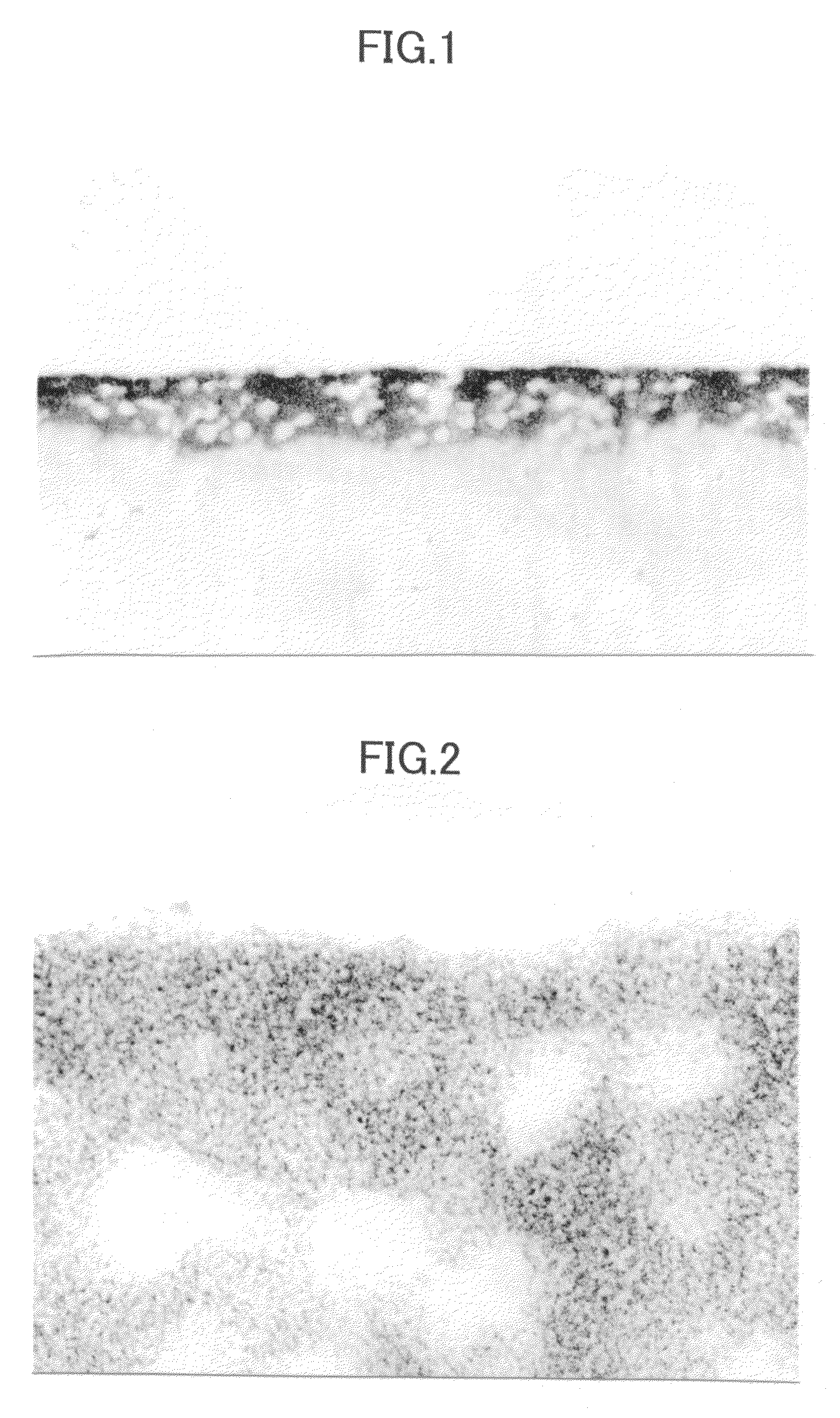
[0063]The plate gained in Embodiment which has a resin-metal composite layer was immersed in a chemical plating bath of Ni—P, which was kept at 40° to deposit a Ni—P plated coating for 10 minutes. The thickness of the deposited Ni—P plated coating is 0.5 μm.

[0064]Then, the plate having plated coating was immersed in an alkali solution, applied 3 A / dn2 of current density as the plated coating being anode and an electrode cathode and, dissolved and removed the plated coating by reverse electrolytic method.

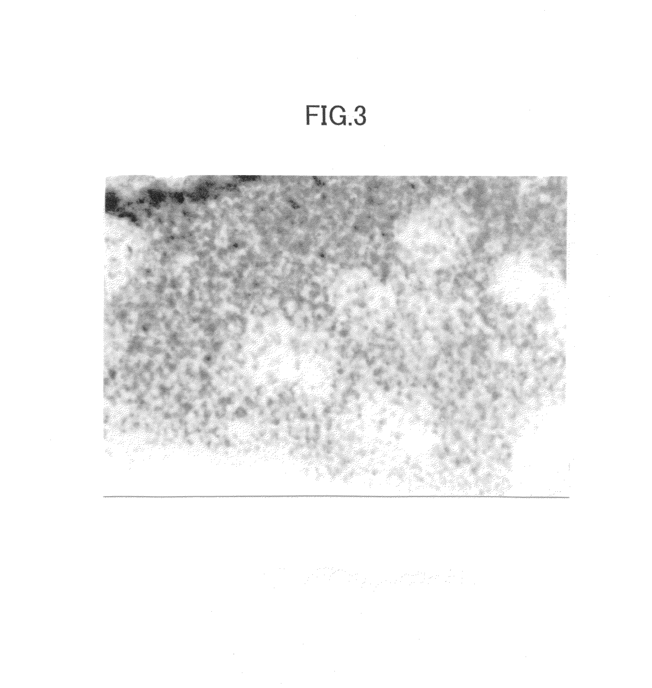
[0065]The TEM picture of the cross-section of the gained treated plate is shown in FIG. 3. It was observed that the metal particles dispersed homogeneously in the range of 100 nm in depth from the surface of the plate. It was also observed that the particle diameter of metal particles became larger in the resin-metal composite layer. The concentration of metal was 80 volume % in the resin-metal composite layer.

embodiment 3

Pre-Treatment Process

[0071]A plate made of polycarbonate resin was prepared and it was immersed in an ozone solution containing 150 ppm of ozone at room temperature for 6 minutes as a pre-treatment process. The surface of the plate was analyzed with FT-IR before and after the pre-treatment process. An absorbing peak was observed in the surface of the plate after the pre-treatment process due to a carbonyl group (—C═O) and a hydroxyl group (—OH).

[0072]

[0073]Next, a composite aqueous solution which dissolves 50 g / L of NaOH (an alkali component) and 1 g / L of sodium lauryl sulfate (anion surface active agent) was heated to 60° C. The plate after pre-treatment process was immersed for 2 minutes.

[0074]

[0075]As soon as completing alkali treatment process, the plate was immersed for 3 minutes in the solution prepared by dissolving 0.1 weight % of silver chloride and 5 weight % of tin chloride in an aqueous solution of 3N hydrochloric acid and heated to 50° C. Then, it was immersed for 3 min...


PUM

PropertyMeasurementUnit
thicknessaaaaaaaaaa
thicknessaaaaaaaaaa
thicknessaaaaaaaaaa

Abstract

A resin-metal composite layer is formed by modifying a surface of a resin substrate to a modified layer, contacting the modified layer with a metal compound solution, and adsorbing at least either metal colloids or ions are adsorbed to the polar group, so that metal particles are dispersed into the modified layer. Because of the fineness of the metal particles in the resin-metal composite layer, high transparent can be achieved. The resin-metal composite layer functions as a transparent conductive layer and the like.

Description

FIELD OF THE INVENTION[0001]The present invention relates to a resin substrate having a resin-metal composite layer and a method for manufacturing thereof. The resin substrate of the present invention has characteristics of conductivity, abrasion resistance, light resistance, flame resistance and the like, because of a resin-metal composite layer. Also, the resin-metal composite layer can be transparent and accordingly, it can be utilized in various fields such as liquid-crystal displays and printed circuit boards, etc.DESCRIPTION OF THE RELATED ART[0002]A resin material has become widely applied to the field metal or the like is conventionally used, because of its formability, highly flexible characteristics of strength, etc., and its light weight. A resin material, however, has disadvantages of nonconductivity, low hardness and the like. In order to solve these problems, a resin material is composed with other materials, such as metals.[0003]For example, one method for giving elec...

Claims


Application Information

Patent Timeline
Patent Type & Authority Patents(United States)
IPC IPC(8): B32B27/32B32B5/16B32B15/04C08J7/06B01J35/02C23C18/08C23C18/18C23C18/31C23C26/00H05K3/18H05K3/38
CPCC23C18/08C23C18/1851C23C18/31H05K3/38C23C18/2033C23C18/2086H05K3/181Y10T428/26H05K2203/1152Y10T428/25H05K2201/2063Y10T428/31504Y10T428/31678
Inventor HIRAOKA, MOTOKIYOSHINAGA, FUMITAKADAIZA, SETSUTOBESSHO, TAKESHI
Owner TOYOTA JIDOSHA KK
Why Eureka
Try Eureka