Minimally invasive heart valve replacement

a heart valve and minimally invasive technology, applied in the field of prosthetic valves, can solve the problems of increasing the risk of embolism, affecting the health of patients, and the valve is too diseased to repair and must be replaced, and achieve the effect of minimal invasiveness

Active Publication Date: 2010-11-23
VENUS MEDTECH (HANGZHOU) INC
View PDF12 Cites 433 Cited by
  • Summary
  • Abstract
  • Description
  • Claims
  • Application Information

AI Technical Summary

Benefits of technology

[0023]It is one aspect of the present invention to provide a prosthetic heart valve with an expandable-collapsible support structure having sufficient flexibility to permit repositioning the valve after its initial placement by reversion to the collapsed stage before final placement.
[0025]The anatomical structure of the apex permits the introduction of various surgical devices and tools into the heart without significant disruption of natural mechanical and electrical heart function. By using such direct access to the heart through the apex, severe size constraints which have been a limitation of endovascular surgical methods of repair / replacement are avoided. In other words, whereas access through the femoral or other vessels in percutaneous endovascular methods are limited to the diameter of the vessel (approximately 8 mm), access through the apex may reasonably avail itself of an opening as large as about 25 mm. Such access to the heart permits greater flexibility with respect to the construction and delivery of a prosthetic valve for minimally invasive delivery.
[0026]The present invention further provides an envelope or anchoring device that may be separate from or part of the collapsible-expandable heart valve; it is formed with distal and proximal sections and is made of a shape-memory material. The design is such that, after the envelope has been inserted through the orifice of an aortic or other valve, a distal section of it everts and wraps around the free ends of the aortic leaflets so as to eventually seat against the aortic or downstream surface of the leaflets, while a main body section expands radially outward and a proximal section swings radially outward to seat against the ventricular or upstream surface of the aortic leaflets. This effectively sandwiches the leaflets between the juxtaposed envelope sections, firmly implanting the envelope at the desired location within the orifice of the defective aortic valve. The implanted envelope thus serves as an anchor for a collapsible-expandable heart valve, which may be separately implanted as a second step and secured thereto via interengaging means provided on the envelope and on a stent portion of the prosthetic heart valve. Alternatively, the envelope can be incorporated as a part of the heart valve stent to allow a single-step implantation.
[0030]In a further particular aspect, the invention provides a minimally invasive method for percutaneously implanting a replacement heart valve in the orifice of a native valve within the human heart, which method comprises providing an intercostal opening in the chest of the patient and an adjacent opening in the apex of the human heart, inserting a first catheter through said openings and through a ventricle of the heart to the location of a diseased valve, deploying a generally tubular anchoring device of shape-memory material from the distal end of said catheter at a location generally interior of the native valve, locating said anchoring device so that, when its shape-memory causes a distal portion thereof to evert, said anchoring device wraps itself around and about the free ends of the native valve leaflets, allowing a central portion of the anchoring device to expand to a greater diameter within the orifice of the native valve and sandwich the leaflets between it and the everted portion, removing the first catheter and inserting a second catheter that includes a replacement valvular device that incorporates an expandable stent loaded on a delivery implement, causing said replacement valvular device to be deployed distally from the open distal end of the catheter, locating the replacement valvular device interior of said implanted anchoring device and allowing the stent to expand in diameter and mate with said anchoring device, and withdrawing the catheter and delivery implement and closing said openings in said heart and the chest of the patient.

Problems solved by technology

Stenosis is one problem that heart valves may develop in which a valve does not open properly, another is insufficiency, or regurgitation, where a valve fails to close properly.
Sometimes such a problem can be treated by surgical repair of a valve; however, often a valve is too diseased to repair and must be replaced.
Mechanical or artificial valves are typically constructed from nonbiological materials, such as plastics, metals and other artificial materials which, while durable, are prone to blood clotting which increases the risk of an embolism.
Anticoagulants which may be taken to prevent blood clotting can possibly complicate a patient's health due to increased risk of hemorrhage.
The major disadvantage of tissue valves is that they lack the long-term durability of mechanical valves.
As a result, the left ventricle has to markedly increase its ventricular chamber pressure to discharge blood past the stenosed aortic orifice; such causes a patient to have syncope, chest pain and difficulty in breathing.
In instances where a patient is deemed operable only at too high a surgical risk, one alternative in valve stenosis has been to dilate the native valve with a balloon catheter to enlarge the valve orifice; however, such practice has experienced a high restenosis rate.
Until recently, simple implantation of a valve prosthesis for the treatment of aortic stenosis without excising the native valve has been considered generally unrealistic because it was deemed difficult to simply superpose an implanted valve on the distorted stenosed native valve.
In some aspects, this intravascular procedure is not only dangerous and tedious because of long tortuous route, but it has limited use because of the catheter size suitable for intravascular insertion.
However, there is only limited space available within the vasculature; thus, the surgical field is often only as large as the diameter of a blood vessel.
Consequently, the introduction of tools and prosthetic devices becomes greatly complicated, and the device to be implanted must be dimensioned and configured to permit it to be introduced into the vasculature, maneuvered therethrough, and then positioned at a desired location.
Delivery of bulky tools and prosthetic devices retrograde through an atheromatous aortic vessel has increased risk of injuring of the atheromatous aortic wall with subsequent potential embolism and even aortic wall rupture.

Method used


Image

  • Minimally invasive heart valve replacement
  • Minimally invasive heart valve replacement
  • Minimally invasive heart valve replacement

Examples


Embodiment Construction

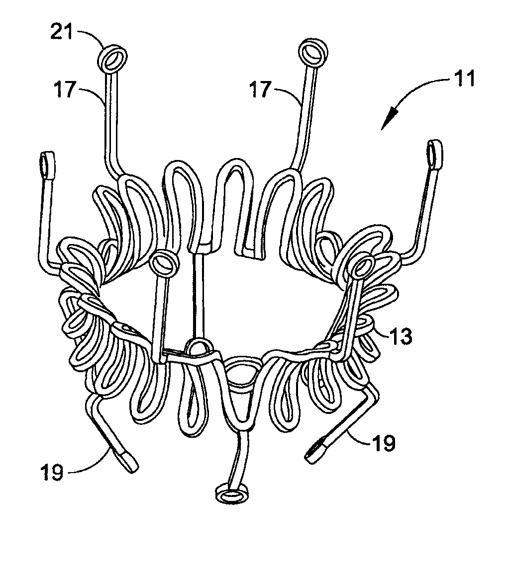
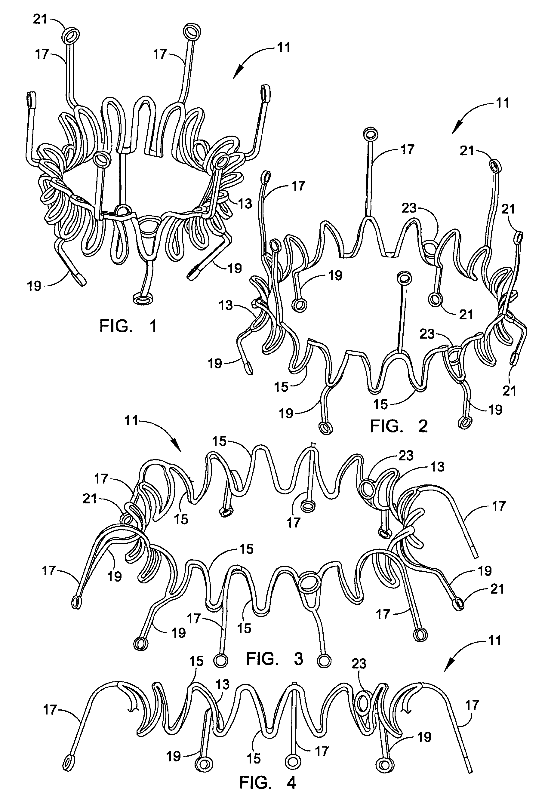
[0053]A first preferred embodiment of an anchoring framework structure 11 for an encapsulation envelope or anchoring device incorporating various features of the invention is shown in FIGS. 1 through 4. The framework has a tubular shape and is designed for anchoring a replacement heart valve at the location of a diseased native valve without excising the native valve. The encapsulation envelope has a tubular deployment form and includes this framework 11 surrounded with a covering layer of biocompatible thin sheet material (not shown). It is designed to be deployed in a collapsed condition using a delivery implement where it is slidably disposed within a catheter that is caused to enter the body through a cannula implanted intercostally in the chest, through which it is directed through the apex region of the heart and, for example, into the left ventricle, and then through the orifice of the aortic valve.

[0054]The encapsulation envelope framework 11 is made of wire-like material, w...


PUM


Abstract

A replacement valve for implantation centrally within the orifice of a malfunctioning native heart valve. The valve is designed for minimally invasive entry through an intercostal opening in the chest of a patient and an opening in the apex of the human heart. The replacement valve includes either a separate anchor (11, 87, 111) or a combined anchor (67) that folds around the malfunctioning native valve leaflets, sandwiching them in a manner so as to securely anchor the replacement valve in a precise, desired location.

Description

CROSS REFERENCE TO RELATED APPLICATIONS[0001]This application is a continuation of International Application No. PCT / IB2007 / 003850 filed 15 Feb. 2007, which claims priority from U.S. Provisional Application No. 60 / 774,821 filed Feb. 16, 2006, the disclosure of which is incorporated by reference.FIELD OF THE INVENTION[0002]The present invention relates to a prosthetic valve for implantation in the heart in a minimally invasive or percutaneous manner, and more particularly to a prosthetic heart valve suitable for replacement of a defective human heart valve, most particularly an aortic valve.BACKGROUND OF THE INVENTION[0003]Four valves in the heart serve to direct the flow of blood through the two sides of the heart in a forward direction. The mitral valve, located between the left atrium and the left ventricle, and the aortic valve, located between the left ventricle and the aorta, constitute the systemic portion of the heart. These two valves direct oxygenated blood coming from the ...

Claims


Application Information

Patent Timeline
Patent Type & Authority Patents(United States)
IPC IPC(8): A61F2/24
CPCA61F2/2418A61F2/2439A61F2/2409A61F2220/0008A61F2250/0059A61F2250/006A61F2230/0013
Inventor GOETZ, WOLFGANGLIM, HOU-SEN
Owner VENUS MEDTECH (HANGZHOU) INC
Why Eureka
Try Eureka