Method and apparatus to produce synthesis gas via flash pyrolysis and gasification in a molten liquid

a technology of flash pyrolysis and gasification, which is applied in the direction of combustible gas production, molten salt/metal gasification, combustible gas purification/modification, etc., can solve the problem of steam reducing the heating value of the resulting product gas, and achieves low cost, low cost, and high efficiency.

Inactive Publication Date: 2011-01-25
US SEC AGRI +1
View PDF20 Cites 18 Cited by
  • Summary
  • Abstract
  • Description
  • Claims
  • Application Information

AI Technical Summary

Benefits of technology

[0030]A particular advantage of the present invention is that it can convert mixed biomass feedstocks into alkane fuels at high efficiency and without the need for an external water source. In the case of “generic” wood as an exemplary biomass reactant, the full conversion of wood to syngas requires an enthalpy increase of 603 kJ / mol. (The overall reaction is C6H9O4+2H2O→6CO+6.5H2. The combustion energy of the resulting syngas, however, is 3,250 kJ / mol. Thus, backward integrating only 19% of the resulting syngas to heat the various molten metal baths is all that is required to make the reactor self-sufficient. The remaining 81% of the product syngas can then be used in conventional fashion, e.g., for direct combustion in a generator, for Fischer-Tropsch synthesis, etc.
[0031]Moreover, because the apparatus is heavily insulated (to limit heat losses), once the apparatus is brought to operating temperatures, there is very little heat loss. Thus, roughly 1% of the syngas needs to be combusted to make up for molten liquid heat losses once the apparatus is up and running. Thus the present invention enables a one-pass, 80% efficient water-gas shift / Fischer-Tropsch reactor (with 20% of the resulting syngas being combusted to heat the gasifier). The conversion of the syngas to iso-octane involves an enthalpy release of −760 kJ / mol. Water is fully recovered and recycled into the process. At 80% efficiency then, the Fischer-Tropsch exothermic heat of 608 kJ / mol is sufficient to dry the incoming biomass reactants. The moisture is recycled for use in the gasification step. Electricity can be generated from a fuel cell operating at the same temperature as the gasification chamber. The electricity so generated can then be used to drive the auger, conveyers, and other ancillary equipment associated with the apparatus of the present invention. Thus, the device can be integrated into a self-powered mobile unit. Biomass is the reactant. The resulting products are syngas (and liquid fuels made from the syngas), electricity, N2 and CO2 exhaust gases, and excess water.
[0032]Thus, the invention is directed to a method and corresponding apparatus for making syngas from biomass. A first version of the apparatus comprises a first molten liquid bath dimensioned and configured to maintain a molten liquid at a first temperature suitable for drying a biomass reactant without degrading the biomass reactant. In this first bath, wet biomass is dried to yield dried biomass and process gas comprising water (and other gases). The first bath is operationally connected to, and dimensioned and configured to transfer molten liquid and dried biomass contained therein to a second molten liquid bath. The second bath is dimensioned and configured to maintain a molten liquid at a second temperature suitable for fast pyrolyzing the dried biomass to yield gas, tar, and char. The second bath is dimensioned and configured to transfer molten liquid, and the gas, tar, and char contained therein to a third molten liquid bath. This third bath is dimensioned and configured to maintain a molten liquid at a third temperature suitable for reforming the gas, tar, and char into synthesis gas. The third bath is dimensioned and configured to transfer molten liquid, tar, and char contained therein to a separator. The separator is dimensioned and configured to separate tar and char from the molten liquid to yield clean molten liquid. The separator is also operationally connected to the first molten liquid bath and is dimensioned and configured to transfer clean molten liquid back to the first molten liquid bath. Lastly, a conduit is operationally connects the first molten liquid bath to the third molten liquid bath. The conduit is dimensioned and configured to transfer process gas from the first molten liquid bath to the third molten liquid bath. Because water from the raw biomass is recycled into the third molten bath, an external source of water is not usually required (depending upon the initial moisture content of the biomass).
[0033]A second version of the apparatus comprises a first molten liquid bath dimensioned and configured to maintain a molten liquid at a first temperature suitable for drying a biomass reactant without degrading the biomass reactant, to yield process gas and dried biomass. A second molten liquid bath, dimensioned and configured to maintain a molten liquid at a second temperature, and suitable for fast pyrolyzing the dried biomass to yield gas, tar, and char, is also provided. A third molten liquid bath dimensioned and configured to maintain a molten liquid at a third temperature suitable for reforming gas, tar, and char into synthesis gas is also provided. A char crusher is interposed between the second molten liquid bath and the third molten liquid bath. The char crusher is dimensioned and configured to crush char into powdered char. A conveyer assembly is provided to move reactants between the various chambers. The conveyor is dimensioned and configured to: (a) move the dried biomass from the first molten liquid bath to the second molten liquid bath; (b) to move char from the second molten method bath to the char crusher; and (c) to move powdered char from the char crusher to the third molten liquid bath. As in the first version of the invention, a conduit is provided that operationally connects the first molten liquid bath to the third molten liquid bath. The conduit is dimensioned and configured to transfer process gas from the first molten liquid bath to the third molten liquid bath.
[0034]The inventive method is a method to convert a biomass reactant into synthesis gas. The method comprises heating biomass in a first molten liquid bath at a first temperature, wherein the first temperature is at least about 100° C., but less than the decomposition temperature of the biomass, wherein process gas comprising water and small amounts of residual air and volatile organic compounds (VOCs) is evaporated from the biomass, thereby yielding dried biomass. The process gas evaporated from the biomass is captured. The dried biomass is heated in a second molten liquid bath at a second temperature, wherein the second temperature is sufficiently high to cause flash pyrolysis of the dried biomass, thereby yielding product gases, tar, and char. Process gas can be added at this point to enhance char gasification immediately after the pyrolysis event. The product gases, tar, and char are then reacted further with the process gas within third molten liquid bath at a third temperature which is equal to or greater than the second temperature within the second molten liquid bath, thereby yielding synthesis gas. A portion of the resulting synthesis gas is combusted to heat the first, second, and third molten liquid baths (unless external natural gas or hydrogen gas is available to be combusted instead).
[0035]The portion of the synthesis gas used to heat the device itself can be combusted to heat the third molten liquid bath only. Heat from the third molten liquid bath is then integrated to heat the second and first molten liquid baths (whose temperatures are lower than the third bath). The biomass reactants can be directly immersed into the various liquid baths, or heated indirectly by placing the biomass reactants within a suitable porous container that allows gas to escape the container but prevents molten liquid from entering the container.

Problems solved by technology

However, injecting steam decreases the heating value of the resulting product gas by increasing the CO2 concentration.

Method used


Image

  • Method and apparatus to produce synthesis gas via flash pyrolysis and gasification in a molten liquid
  • Method and apparatus to produce synthesis gas via flash pyrolysis and gasification in a molten liquid
  • Method and apparatus to produce synthesis gas via flash pyrolysis and gasification in a molten liquid

Examples


first embodiment

Continuous Gasifier—First Embodiment

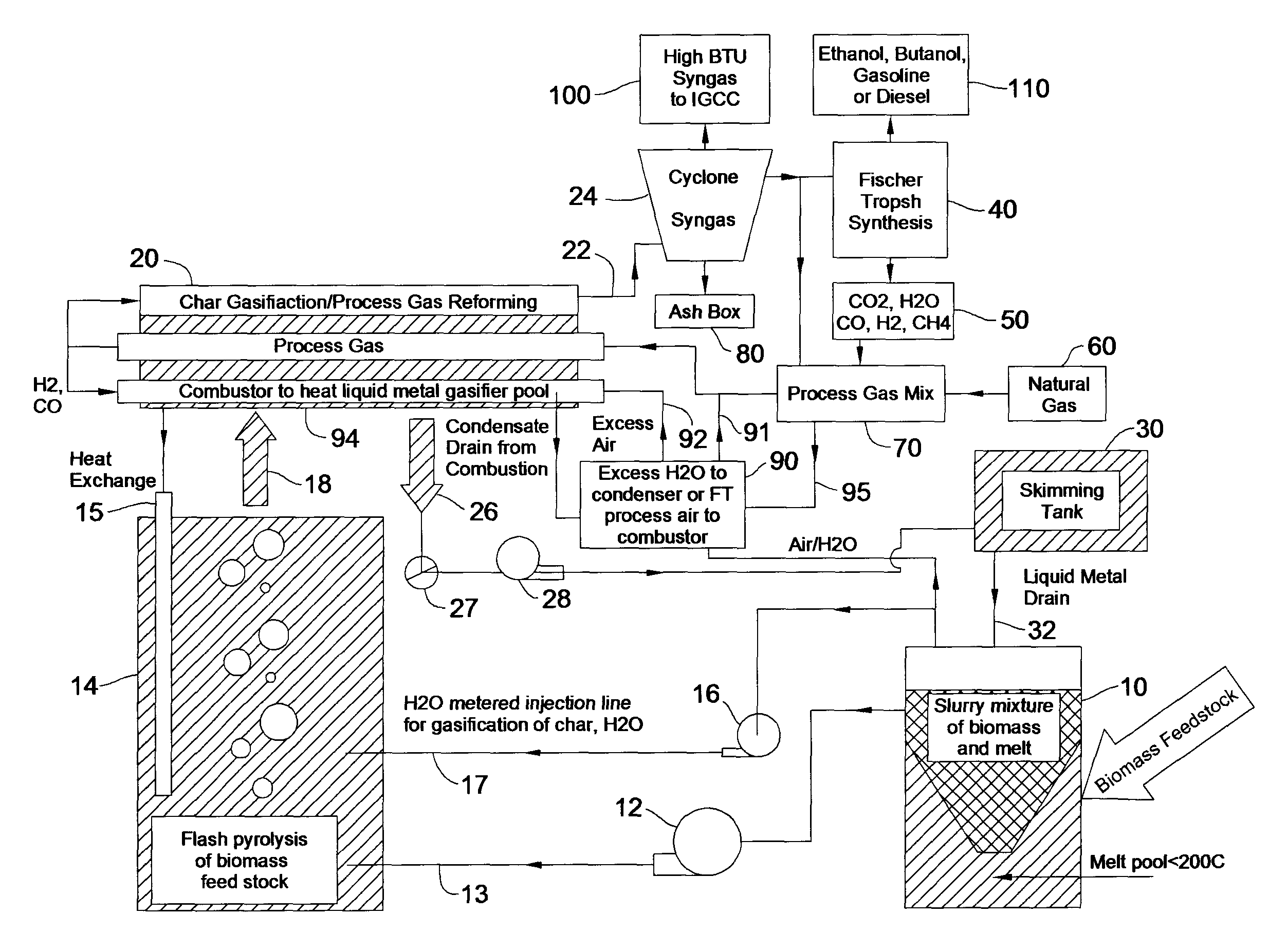
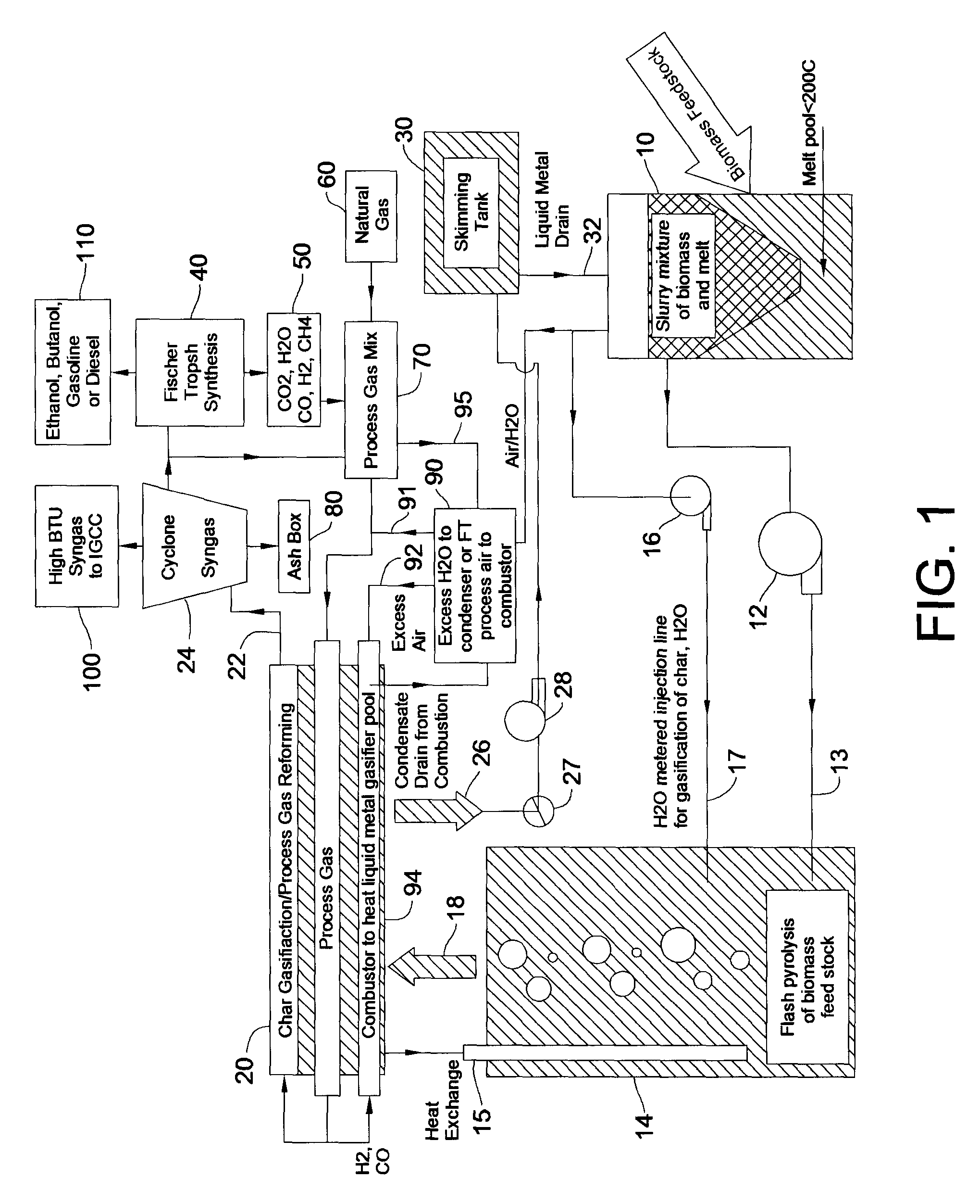
[0066]A first version of the invention is a continuous gasifier comprising four main chambers, each chamber having a distinct function. The following discussion is made in reference to FIG. 1, which is a schematic rendering of this first embodiment of the invention. A stirred mixing and drying chamber 10 mixes the biomass with a molten metal at a temperature range that causes rapid water evaporation from the biomass, yet is below the degradation temperature of the biomass. This temperature range is from 100° C. (i.e., the boiling point of water) to about 300° C., with a temperature of about 200° C. or less being generally preferred. Preferably, the biomass is inserted into mixing and drying chamber 10 at atmospheric pressure, near the bottom center of the chamber. The chamber's mixing blades ensure that the floating biomass is adequately mixed with the molten metal-biomass slurry exiting the chamber.

[0067]The molten metal-biomass slurry is then tr...

examples

[0106]The following Examples are included solely to provide a more complete description of the invention disclosed and claimed herein. The Examples do not limit the scope of the invention in any fashion.

Bench-Scale Test Equipment:

[0107]To provide a scale-up relationship with a pilot-scale gasifier, a bench-scale reactor according to the present invention was fabricated and used to test flash pyrolysis results using varying sizes of feedstock wafers and varying feedstock moisture levels. The test device included a primary molten-metal chamber deep enough to test various reaction pressures and reaction times. The device likewise included a host of sensors so as to characterize the process with dynamic measurements of heating and syngas bubble growth. The test device also was able to measure the contents of the developing and bursting syngas bubble to measure the degree of biomass conversion.

Liquid Metal Bath Chamber and Heating:

[0108]The main variable affecting the dimensions of the m...


PUM

PropertyMeasurementUnit
temperatureaaaaaaaaaa
boiling pointaaaaaaaaaa

Abstract

Disclosed are a method and a corresponding apparatus for converting a biomass reactant into synthesis gas. The method includes the steps of (1) heating biomass in a first molten liquid bath at a first temperature, wherein the first temperature is at least about 100° C., but less than the decomposition temperature of the biomass, wherein gas comprising water is evaporated and air is pressed from the biomass, thereby yielding dried biomass with minimal air content. (2) Recapturing the moisture evaporated from the biomass in step 1 for use in the process gas. (3) Heating the dried biomass in a second molten liquid bath at a second temperature, wherein the second temperature is sufficiently high to cause flash pyrolysis of the dried biomass, thereby yielding product gases, tar, and char. (4) Inserting recaptured steam into the process gas, which may optionally include external natural gas or hydrogen gas or recycled syngas for mixing and reforming with tar and non-condensable gases. (5) Further reacting the product gases, tar, and char with the process gas within a third molten liquid bath at a third temperature which is equal to or greater than the second temperature within the second molten liquid bath, thereby yielding high quality and relatively clean synthesis gas after a relatively long residence time needed for char gasification. A portion of the synthesis gas so formed is combusted to heat the first, second, and third molten liquid baths, unless external natural or hydrogen gas is available for this use.

Description

CROSS-REFERENCE TO RELATED APPLICATIONS[0001]Priority is hereby claimed to provisional application Ser. No. 60 / 913,681, filed Apr. 24, 2007, which is incorporated herein by reference.FEDERAL FUNDING STATEMENT[0002]This invention was made with United States government support awarded by the following agency: USDA / FS 06-JV11111136-104. The United States has certain rights in this invention.FIELD OF THE INVENTION[0003]The invention is directed to a method and corresponding apparatus to produce synthesis gas from solid biomass by pyrolyzing and gasifying the biomass in a pool of liquid metal.BACKGROUND[0004]Since the early 1900's, efforts have been made to develop an efficient means to convert solid, carbon-containing reactants into liquid fuels. The early work in the field was performed in Germany in the years prior to and between the two world wars. In 1912-13, Frederick Bergius described the fundamental process for hydrogenating coal under very high pressure to yield liquid fuels. (B...

Claims


Application Information

Patent Timeline
Patent Type & Authority Patents(United States)
IPC IPC(8): C01B3/36C01B3/02C01B3/12C10J3/46B01J7/00C10B1/00C10J1/207
CPCC10J3/463C10J3/57C10J3/66C10K1/026C10J2300/0909C10J2300/0916C10J2300/092C10J2300/0946C10J2300/0973C10J2300/0989C10J2300/1659C10J2300/1823Y02E20/18Y02E50/32Y02E50/30Y02P20/145
Inventor DIETENBERGER, MARK A.ANDERSON, MARK H.
Owner US SEC AGRI
Why Eureka
Try Eureka