Shallow trench capacitor compatible with high-K / metal gate

a capacitor and trench technology, applied in the field of forming capacitors, to achieve the effect of improving performance, less expensive to implement, and increasing the area density of capacitors

Inactive Publication Date: 2011-01-25
GLOBALFOUNDRIES US INC
View PDF16 Cites 18 Cited by
  • Summary
  • Abstract
  • Description
  • Claims
  • Application Information

AI Technical Summary

Benefits of technology

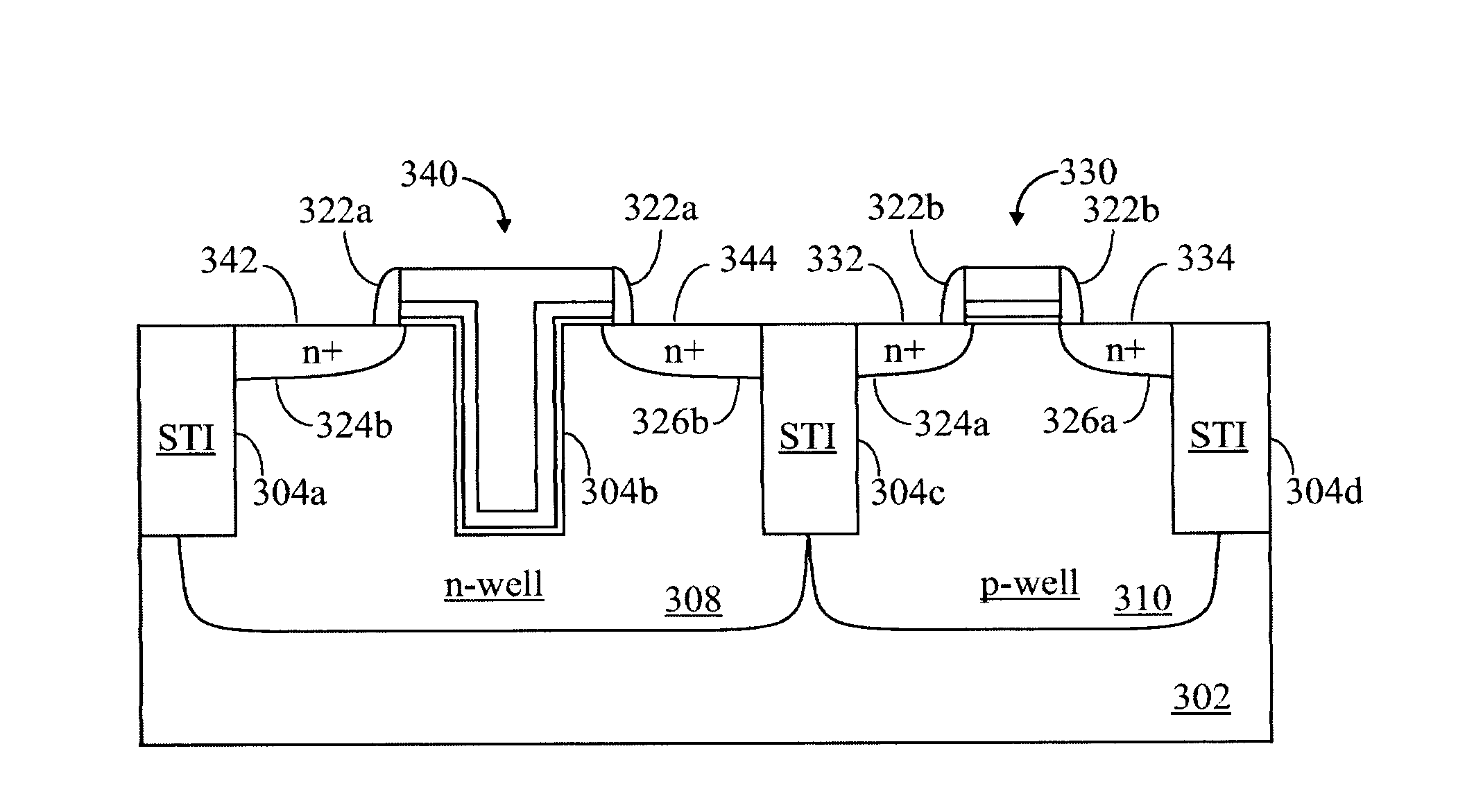
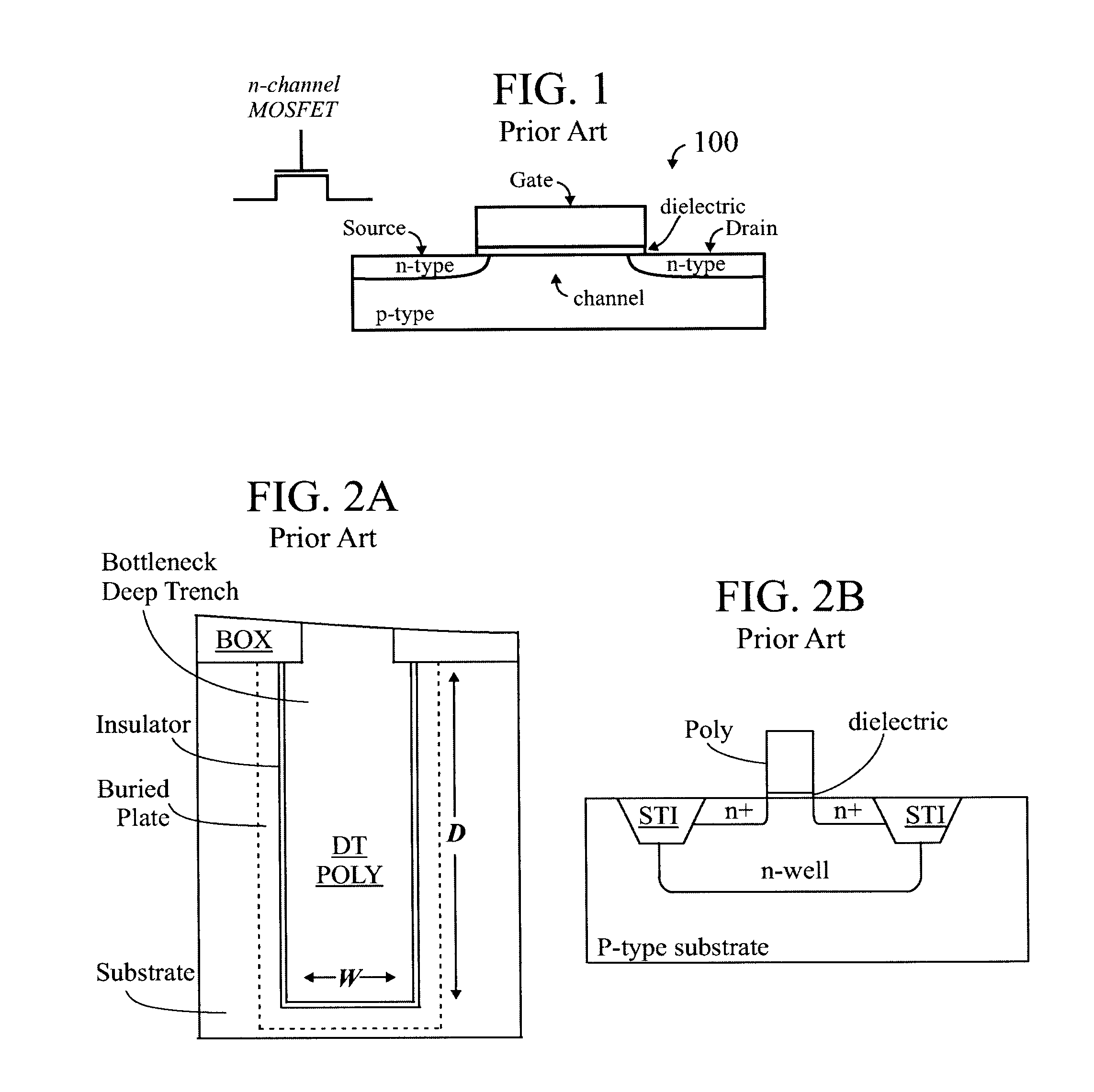
[0039]The invention is generally directed to a minimal process add “shallow” trench (ST) capacitor. The design of the shallow trench capacitor disclosed herein allows for ESR comparable to planar (MOS) caps, with more than 3× capacitance / area density increase. The shallow trench (ST) capacitor disclosed herein may be slightly more expensive than a MOS cap, but offers better performance than the MOS cap. Compared with deep trench (DT) capacitors, the shallow trench (ST) capacitor is simpler and less expensive to implement, since the DT capacitor etch adds more steps (such as the DT etch itself, and one or more poly depositions), and is thus more expensive. The DT capacitor offers more performance, but only at a cost. Although the DT capacitor may offer more capacitance per top-down area than the ST capacitor disclosed herein, the DT capacitor may have significantly more ESR than the ST capacitor.
[0045]Furthermore, the shallow trench capacitor provides superior high-frequency performance without using extra ion implantation process.

Problems solved by technology

Compared with deep trench (DT) capacitors, the shallow trench (ST) capacitor is simpler and less expensive to implement, since the DT capacitor etch adds more steps (such as the DT etch itself, and one or more poly depositions), and is thus more expensive.

Method used


Image

  • Shallow trench capacitor compatible with high-K / metal gate
  • Shallow trench capacitor compatible with high-K / metal gate
  • Shallow trench capacitor compatible with high-K / metal gate

Examples


Embodiment Construction

[0061]In the description that follows, numerous details are set forth in order to provide a thorough understanding of the present invention. It will be appreciated by those skilled in the art that variations of these specific details are possible while still achieving the results of the present invention. Well-known processing steps and materials are generally not described in detail in order to avoid unnecessarily obfuscating the description of the present invention.

[0062]Throughout the descriptions set forth in this disclosure, lowercase numbers or letters may be used, instead of subscripts. For example Vg could be written Vg. Generally, lowercase is preferred to maintain uniform font size.) Regarding the use of subscripts (in the drawings, as well as throughout the text of this document), sometimes a character (letter or numeral) is written as a subscript—smaller, and lower than the character (typically a letter) preceding it, such as “Vs” (source voltage) or “H2O” (water). For c...


PUM


Abstract

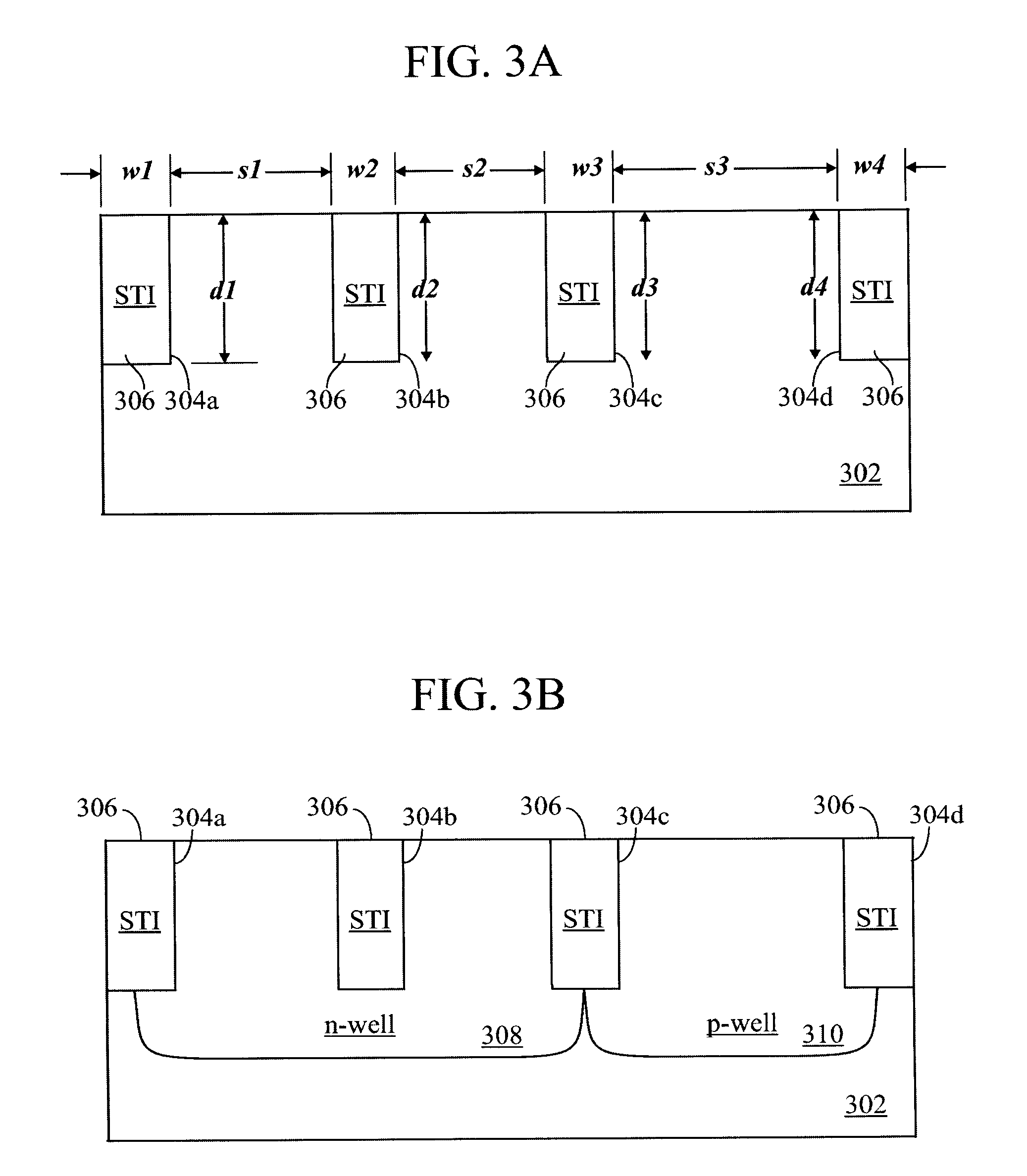
Forming a shallow trench capacitor in conjunction with an FET by forming a plurality of STI trenches; for the FET, implanting a first cell well having a first polarity between a first and a second of the STI trenches; for the capacitor, implanting a second cell well having a second polarity in an area of a third of the STI trenches; removing dielectric material from the third STI trench; forming a gate stack having a first portion located between the first and the second of the STI trenches and a second portion located over and extending into the third trench; and performing a source / drain implant of the same polarity as the second cell well, thereby forming a FET in the first cell well, and a capacitor in the second cell well. The second polarity may be opposite from the first polarity. An additional implant may reduce ESR in the second cell well.

Description

FIELD OF THE INVENTION[0001]The invention relates to semiconductor devices and, more particularly to forming capacitors, such as decoupling capacitors.BACKGROUND OF THE INVENTION[0002]The transistor is a solid state semiconductor device which can be used for amplification, switching, voltage stabilization, signal modulation and many other functions. Generally, a transistor has three terminals, and a voltage applied to a specific one of the terminals controls current flowing between the other two terminals. One type of transistor is known as the field effect transistor (FET).[0003]The terminals of a field effect transistor (FET) are commonly named source, gate and drain. In the FET, a small amount of voltage is applied to the gate (G) in order to control current flowing between the source (S) and drain (D). In FETs, the main current appears in a narrow conducting channel formed near (usually primarily under) the gate. This channel connects electrons from the source terminal to the dr...

Claims


Application Information

Patent Timeline
Patent Type & Authority Patents(United States)
IPC IPC(8): H01L27/108
CPCH01L27/0629
Inventor BOOTH, JR., ROGER A.BRODSKY, MARYJANECHENG, KANGGUOPEI, CHENGWEN
Owner GLOBALFOUNDRIES US INC
Why Eureka
Try Eureka