Amorphous-carbon-based hard multilayer film and hard surface member having the film on surface

a multi-layer film and amorphous carbon technology, applied in the field of members, can solve the problem of low adhesion of the film to various kinds of substrates

Inactive Publication Date: 2011-02-15
KOBE STEEL LTD
View PDF20 Cites 18 Cited by
  • Summary
  • Abstract
  • Description
  • Claims
  • Application Information

AI Technical Summary

Benefits of technology

[0007]It is desirable to provide an amorphous carbon (DLC) film having excellent adhesion at high temperature.
[0008]Furthermore, it is desirable to provide an amorphous carbon (DLC) film having excellent adhesion in a high load region.
[0009]As a result of earnest study, the inventors found that when a nitride or a carbo-nitride is used for the intermediate layer, adhesion of the amorphous carbon (DLC) film can be improved even at high temperature or in a high load region, and consequently completed an embodiment of the invention.
[0018]According to the embodiment of the invention, since the intermediate layer is formed by the base layer including a nitride or a carbo-nitride, and a layer in which a composition is changed from the base layer to the amorphous carbon (DLC) film, adhesion between the substrate and the amorphous carbon (DLC) film can be improved even at high temperature and in a high load region.

Problems solved by technology

However, on the other hand, the excellent chemical stability of an amorphous carbon (DLC) film means low adhesion of the film to various kinds of substrates.

Method used


Image

  • Amorphous-carbon-based hard multilayer film and hard surface member having the film on surface
  • Amorphous-carbon-based hard multilayer film and hard surface member having the film on surface

Examples


example 1

[0045]Unbalanced magnetron sputtering apparatus having four evaporation sources (6 inches in target diameter) was used, and a target including each of elements M shown in the following Table 1 was mounted for two evaporation sources, and a carbon target was mounted for the remained, two evaporation sources. Mirror-polished substrates (cemented carbide (JIS-P20) substrate and high speed tool steel (JIS-SKH51, HRC63)) substrate were subjected to ultrasonic cleaning in ethanol, and then mounted on a turntable in a chamber of the sputtering apparatus. The chamber was evacuated (to a pressure of 1×10⁻³ Pa), and the substrates were heated to about 200° C. and then etched by Ar ions.

[0046]Next, a base layer, compositional gradient layer, and DLC layer as shown in the following Table 1 were formed in this order as follows.

1) Base Layer

[0047]A predetermined, atmospheric gas was introduced into the chamber, and each of the targets including the element M was supplied with electric power of 2 ...

example 2

[0075]A base layer, compositional gradient layer, and DLC layer as shown in the following Table 2 were formed and evaluated in the same way as in the example 1. A crystal structure of the base layer was examined by X-ray diffraction (CuKα line, 40 kV-40 mA) using the θ-2θ method, and a crystal structure corresponding to a peak having the highest intensity was determined as a crystal structure of the base layer.

[0076]Results are shown in Table 2. In the table, each sample in which a crystal structure of the base layer is made to be the α-W structure, α-Mo structure or TaN structure exhibits intensity of a maximum peak of the α-W structure, α-Mo structure, or TaN structure, showing at least five times as large as intensity of peaks of other crystal structures.

[0077]

TABLE 2CompositionAdhesionBase LayerChange LayerDLC layer(Critical Load (N))Element MCompositionThicknessCrystalThicknessCompositionThicknessSintered HardHigh Speed ToolNo.(Target)(Atomic Ratio)(nm)StructureType*(nm)(Atomic...

example 3

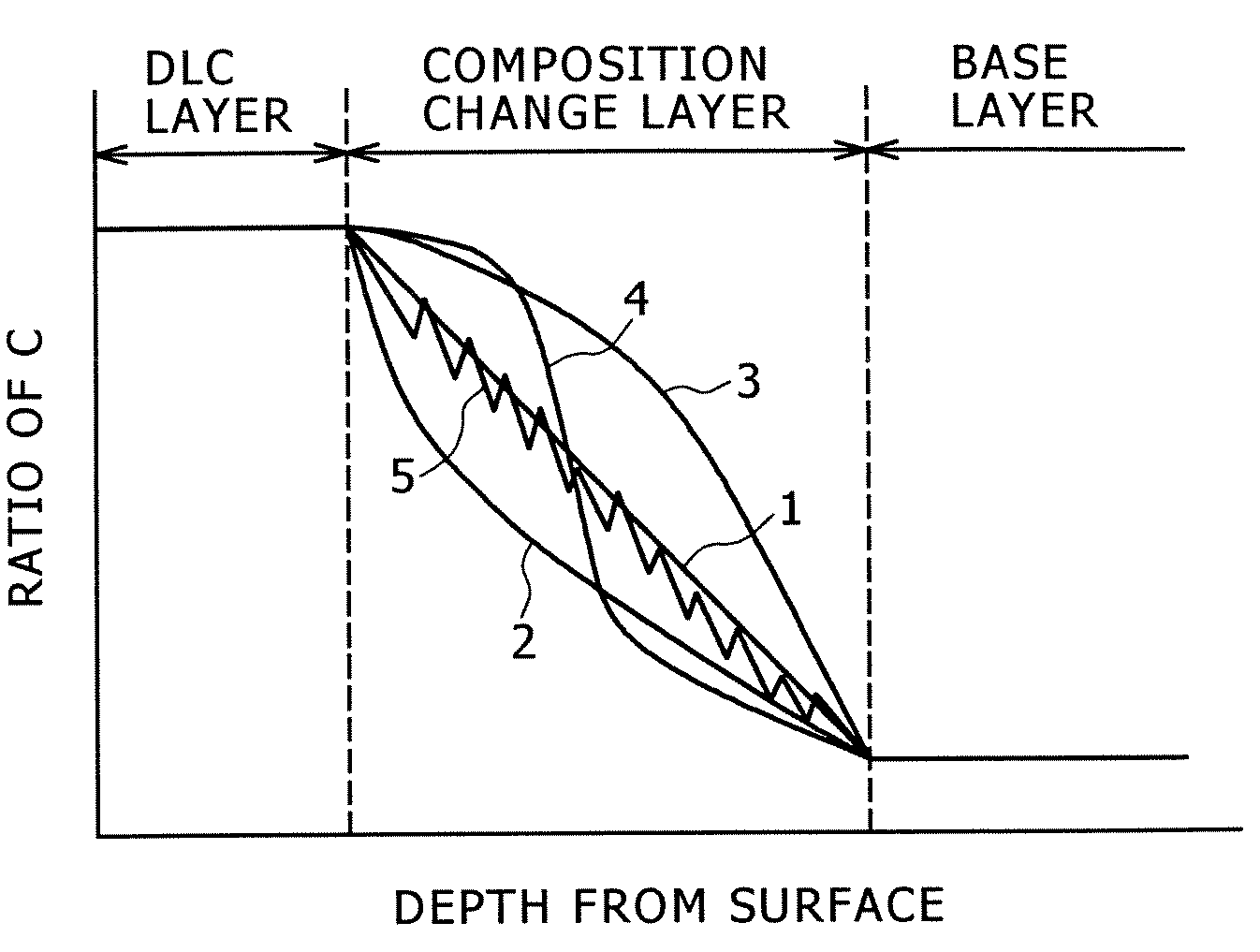
[0080]A base layer, compositional gradient layer, and DLC layer as shown in the following Table 3 were formed and evaluated in the same way as in the example 1. In samples of Nos. 19 to 23, a composition change pattern of the compositional gradient layer was variously changed as shown in FIG. 1.

[0081]

TABLE 3CompositionBase LayerChange LayerDLC LayerAdhesionElement MCompositionThicknessThicknessCompositionThickness(Critical Load (N))No.(Target)(Atomic Ratio)(nm)Type*(nm)(Atomic Ratio)(μm)Sintered Hard AlloyHigh Speed Tool Alloy1WW0.8N0.21001500C2100 or more902WW0.7C0.1N0.21001500C2100 or more853WW0.5C0.3N0.21001500C280754WW0.4C0.5N0.11001500C280705WW0.4C0.61001500C270606MoMo0.85N0.1501500C250457MoMo0.85N0.1551500C270658MoMo0.85N0.15101500C295859MoMo0.85N0.151001500C2100 or more8510MoMo0.85N0.152001500C2100 or more8511MoMo0.85N0.1520001500C2100 or more8012MoMo0.85N0.151000001500C2100 or more8013WW0.8N0.210010C2504014WW0.8N0.210015C2908515WW0.8N0.2100120C2958516WW0.8N0.21001100C2100 or...


PUM

PropertyMeasurementUnit
thicknessaaaaaaaaaa
thicknessaaaaaaaaaa
thicknessaaaaaaaaaa

Abstract

An amorphous carbon (DLC) film having excellent adhesion at high temperature is provided. An amorphous-carbon-based hard multilayer film, which is formed on a surface of a substrate, includes a base layer formed at a substrate side, a surface layer formed at a surface side, and a compositional gradient layer formed between the base layer and the surface layer, wherein the base layer includes a nitride or a carbo-nitride of an element M expressed by the following formula (1), the surface layer includes an amorphous carbon film containing C of 50 atomic percent or more, and the compositional gradient layer is a layer in which the element M and nitrogen are decreased, and carbon is increased from the base layer to the amorphous carbon film:M1-x-yCxNy  (1),(wherein M is at least one selected from a group 4A element in the periodic table, a group 5A element, a group 6A element, Al, and Si, and x and y denote atomic ratios in the formula, and x is 0.5 or less, y is 0.03 or more, and 1-x-y is more then 0).

Description

BACKGROUND OF THE INVENTION[0001]1. Field of the Invention[0002]The present invention relates to a member (hard surface member) having a hard coating such as a sliding component of a machine, and a cutting tool.[0003]2. Description of the Related Art[0004]An amorphous carbon film is known as a hard coating. Amorphous carbon has an intermediate structure between diamond and graphite carbon being mixed with each other, and may be called hard amorphous carbon, formless carbon, hard formless carbon, i-carbon, or diamond like carbon (DLC). Since the amorphous carbon (hereinafter, sometimes called DLC) has high hardness as diamond, and has excellent wear resistance, solid lubricating ability, heat conductivity, and chemical stability, it is being used for protective films for various components such as sliding members, dies, cutting tools, wear-resistant machine parts, abradants, and magnetic / optical components. In particular, the amorphous carbon (DLC) is practically used for a coating o...

Claims


Application Information

Patent Timeline
Patent Type & Authority Patents(United States)
IPC IPC(8): B32B9/00
CPCC23C14/022C23C14/027C23C14/352C23C14/0605Y10T428/30Y10T428/24942Y10T428/31678C23C28/00C23C14/35
Inventor YAMAMOTO, KENJIMATSUKADO, KATSUHIRO
Owner KOBE STEEL LTD
Why Eureka
Try Eureka