Composite resonance circuit and oscillation circuit using the circuit
a resonance circuit and circuit technology, applied in the field of complex resonance circuits, can solve the problems of no other, oscillation circuit, etc., and achieve the effects of reducing electric current consumption, high impedance, and reducing voltage applied
- Summary
- Abstract
- Description
- Claims
- Application Information
AI Technical Summary
Benefits of technology
Problems solved by technology
Method used
Image
Examples
first embodiment
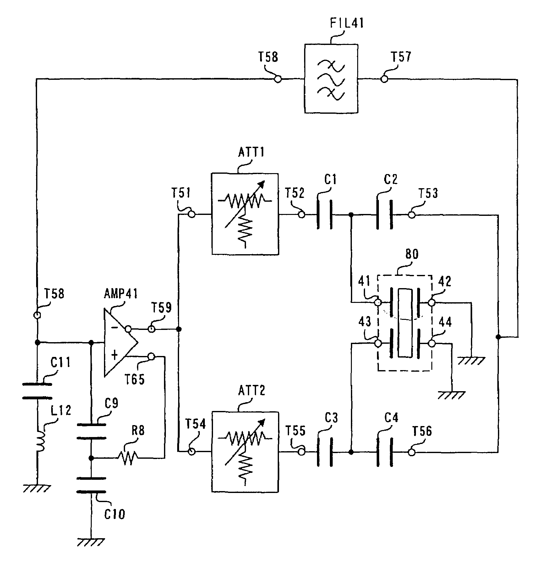
[0084]the complex resonance circuit according to the present invention, in which the piezoelectric substrate formed from a piezoelectric material (quartz substrate) is utilized, is also referred to as a “complex resonator”. A principle of the present invention, which will be described in reference to the following drawings, is not limited to the embodiments. The complex resonance circuit according to the present invention includes a complex resonance circuit having other piezoelectric materials such as a ceramic. The complex resonance circuit may be configured by at least one strip line element.
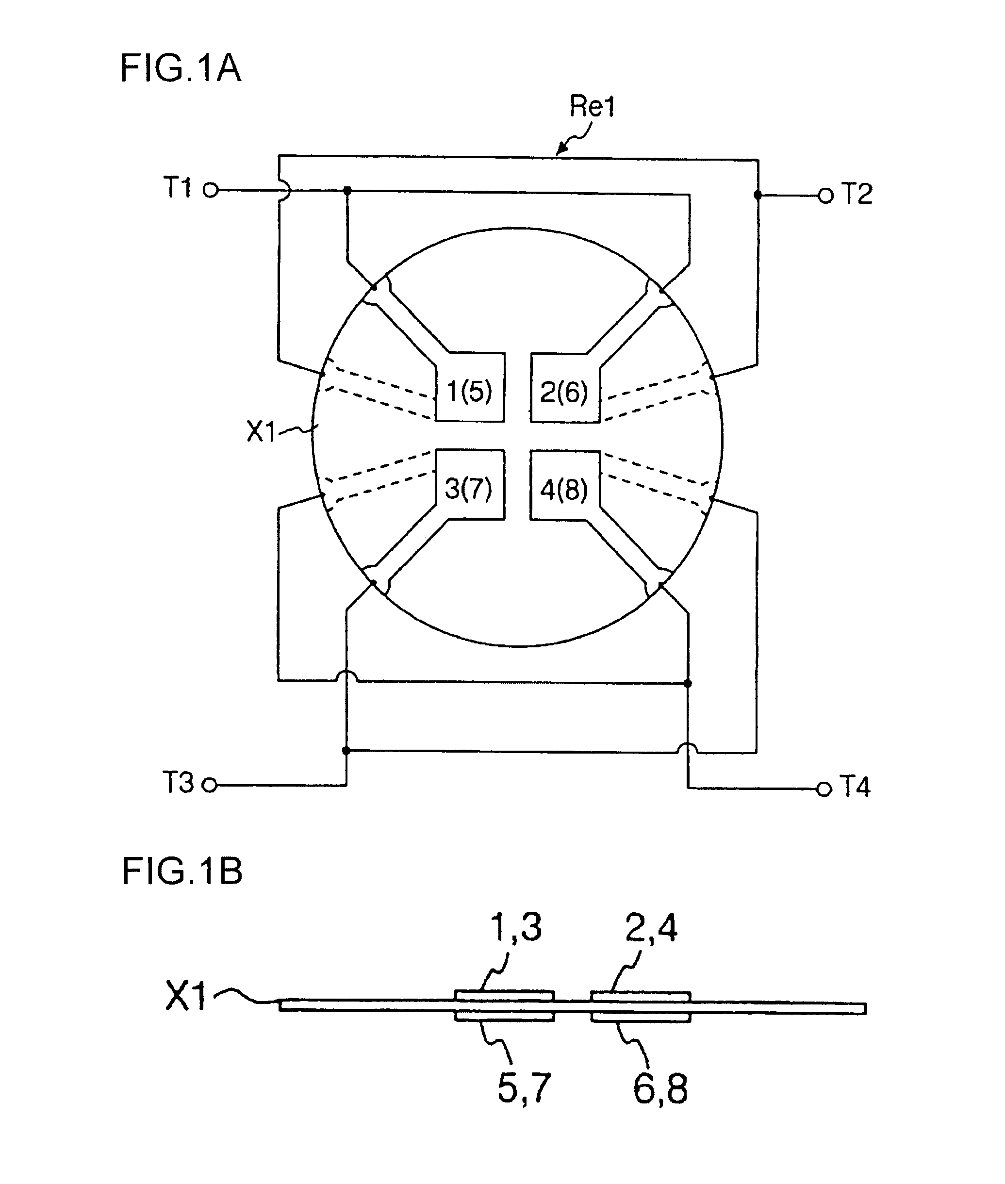
[0085]As shown in FIGS. 1A and 1B, a complex resonator Re1 includes, a first electrode 1, a second electrode 2, a third electrode 3, and a fourth electrode 4 adjacently formed on a front surface of the disciform quartz piezoelectric substrate X1. The first electrode 1, the second electrode 2, the third electrode 3, and the fourth electrode 4 face to each other. The complex resonator Re1 furth...
second embodiment
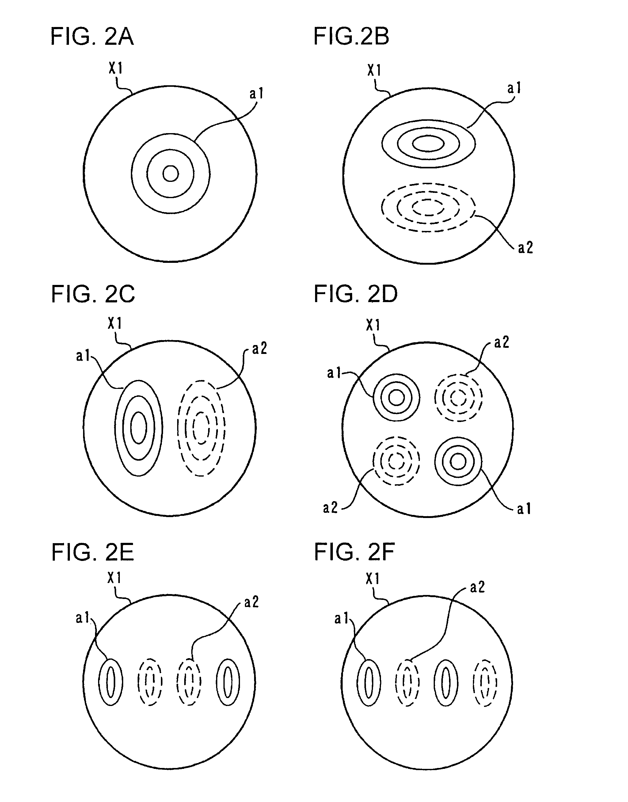
[0161]A first variation of second embodiment will now be described with reference to FIG. 11B. In an electrode structure shown in FIG. 11B, an interdigital electrode pair of 31 and 33 and an interdigital electrode pair of 35 and 37 are serially disposed. Natural vibration modes excited by an AC current supplied across external terminals T23 and T24 are as shown in FIGS. 2E and 2F.
[0162]According to the first variation of second embodiment utilizing the natural vibration modes shown in FIGS. 2C and 2E, an antiresonance frequency can be adjusted by changing a driving signal level.
[0163]As shown in FIGS. 1A, 9, and 10, the embodiments having the electrode structures having the electrodes formed on both the front and rear surfaces of the quartz substrate utilizes the bulk wave vibration modes such as a thickness shar vibration. A second variation of the second embodiment of the complex resonance circuit having interdigital electrodes, which also utilizes bulk waves of a thickness shear ...
third embodiment
[0173]In the present invention, the electrodes 61, 61′, 62, and 62′ are formed on the four surfaces of the upper part 52 as shown in FIGS. 13B and 13C and connected as shown in FIG. 13C. In addition, electrodes separated at a center of the lower part 53 are formed as shown in FIG. 13D. The electrodes of the lower part 53 are different from the conventional tuning-fork type bending resonator.
[0174]As shown in FIG. 13D, eight electrodes 71 to 74 and 71′ to 74′ are formed on the lower part 53. The configuration of the eight electrodes will now be described from a view point of operations thereof. The third embodiment of the present invention includes the twin-tuning fork structure in which four electrodes shown in FIG. 13C are respectively formed on four surfaces of the upper part 52 and eight electrodes shown in FIG. 13D are formed on four surfaces of the lower part 53. The four electrodes of the upper part 52 are connected to the external electrodes 41 and 42 as shown in FIG. 13C. Th...
PUM
 Abstract
Description
Claims
Application Information
 - R&D
- Intellectual Property
- Life Sciences
- Materials
- Tech Scout
- Unparalleled Data Quality
- Higher Quality Content
- 60% Fewer Hallucinations
Browse by: Latest US Patents, China's latest patents, Technical Efficacy Thesaurus, Application Domain, Technology Topic, Popular Technical Reports.
© 2025 PatSnap. All rights reserved.Legal|Privacy policy|Modern Slavery Act Transparency Statement|Sitemap|About US| Contact US: help@patsnap.com


