Multiple detection systems

a detection system and multi-stage technology, applied in the field of particle detection systems, can solve the problems of reducing the m/z resolving power, affecting the detection efficiency of particle separators, and often insufficient gain to produce measurable output signals from single ions, so as to reduce cost and complexity, improve signal-to-noise, and increase intensities

Inactive Publication Date: 2011-04-19
PERKINELMER HEALTH SCIENCES INC
View PDF30 Cites 35 Cited by
  • Summary
  • Abstract
  • Description
  • Claims
  • Application Information

AI Technical Summary

Benefits of technology

[0021]It is another object of the present invention to provide methods and apparatus for the recording of particle signals with improved temporal resolving power and measurement accuracy compared to prior detection systems.
[0040]In another preferred method of the present invention, the number of spectra that are accumulated to produce a net integrated spectrum from each anode of a multiple-detector arrangement may be different for each detector. For example, a detector and associated electronics that is optimized to record low intensity signals may integrate a greater number of spectra than the detector and associated electronics of the other detector which is optimized for signals with greater intensities. For the situation in which the detectors are used alternately, rather than simultaneously, and the total integration time is divided between the two detectors, a better signal-to-noise is achieved than if each detector integrated the same number of spectra.

Problems solved by technology

Because ions arriving at the detector of a ToF mass spectrometer are typically dispersed over some distance orthogonal to the ToF analyzer axis direction, a non-planar detector surface will produce a variation in flight distances, and therefore flight times, for ions of any particular m / z value, resulting in a degradation of the m / z resolving power.
Generally, detectors of all types are limited by practical considerations in the maximum absolute amplitude of output signal that can be produced.
However, this gain is often insufficient to produce a measurable output signal from single ions or from some few ions arriving at the detector simultaneously.
Nevertheless, as discussed above, the total signal dynamic range that may be achieved may be limited, in part, by the detector response characteristics when operated at a fixed gain.
Unfortunately, it is usually impractical or undesirable in practice to rapidly adjust the gain of the detector from the acquisition of one spectrum to the next, because it is generally necessary to allow some time, typically on the order of milliseconds or longer, for the detector response to stabilize after the gain is changed.
This delay would result in a severe reduction of the speed with which ToF spectra may be recorded, leading to a loss of sensitivity within a fixed acquisition time.
Further, spectral acquisition speed is important in itself in many time-dependent analyses, such as when a mass spectrometer is used as a detector for a gas or liquid chromatographic separation, and a reduction in spectral acquisition speed would restrict the resolving power of the chromatographic separation.
Otherwise, a significant number of single ions that produce detector output pulses with amplitudes that fall within the lower-amplitude region of the pulse height distribution, will not be recorded, resulting in substantial error in the intensities of small m / z peaks relative to that of large m / z peaks in a spectrum.
Then, however, a significant number of single ion hits may not produce a signal amplitude at the ADC input that is large enough to register 1 bit count in the ADC output, resulting in substantial inaccuracies in the relative intensities of less intense m / z peaks in the measured spectrum.
On the other hand, the TDC approach is severely restricted in dynamic range within individual spectra, because a TDC is unable to distinguish between the arrival of a single ion and the simultaneous arrival of more than one ion.
Therefore, the use of a TDC to record m / z spectra is limited to situations in which the ion flux is low enough to ensure that the probability of arrival of more than one ion within the dead time of the TDC is less than about 0.1 for the most intense peaks in a m / z spectrum.
Hence, the use of a TDC for accurate measurement of relative ion abundances is limited to analytical situations in which the ion flux is relatively low, and in which sufficient time is available to integrate enough individual spectra to achieve acceptable signal dynamic range.
This approach still limits, however, the signal dynamic range that may be accommodated within a m / z spectrum to the inherently limited linear dynamic range of the multiplier.
However, these types of structures do not typically produce output signals with as fast a response time as that from a so-called ‘channel-plate’ electron multiplier (CPEM).
However, because of its compact structure, it is not possible or practical to incorporate an intermediate collector electrode at an intermediate stage of multiplication.
This approach obviously becomes very cumbersome and expensive to implement due to the multiplicity of parallel TDC counting electronics that are required.

Method used


Image

  • Multiple detection systems
  • Multiple detection systems
  • Multiple detection systems

Examples


Embodiment Construction

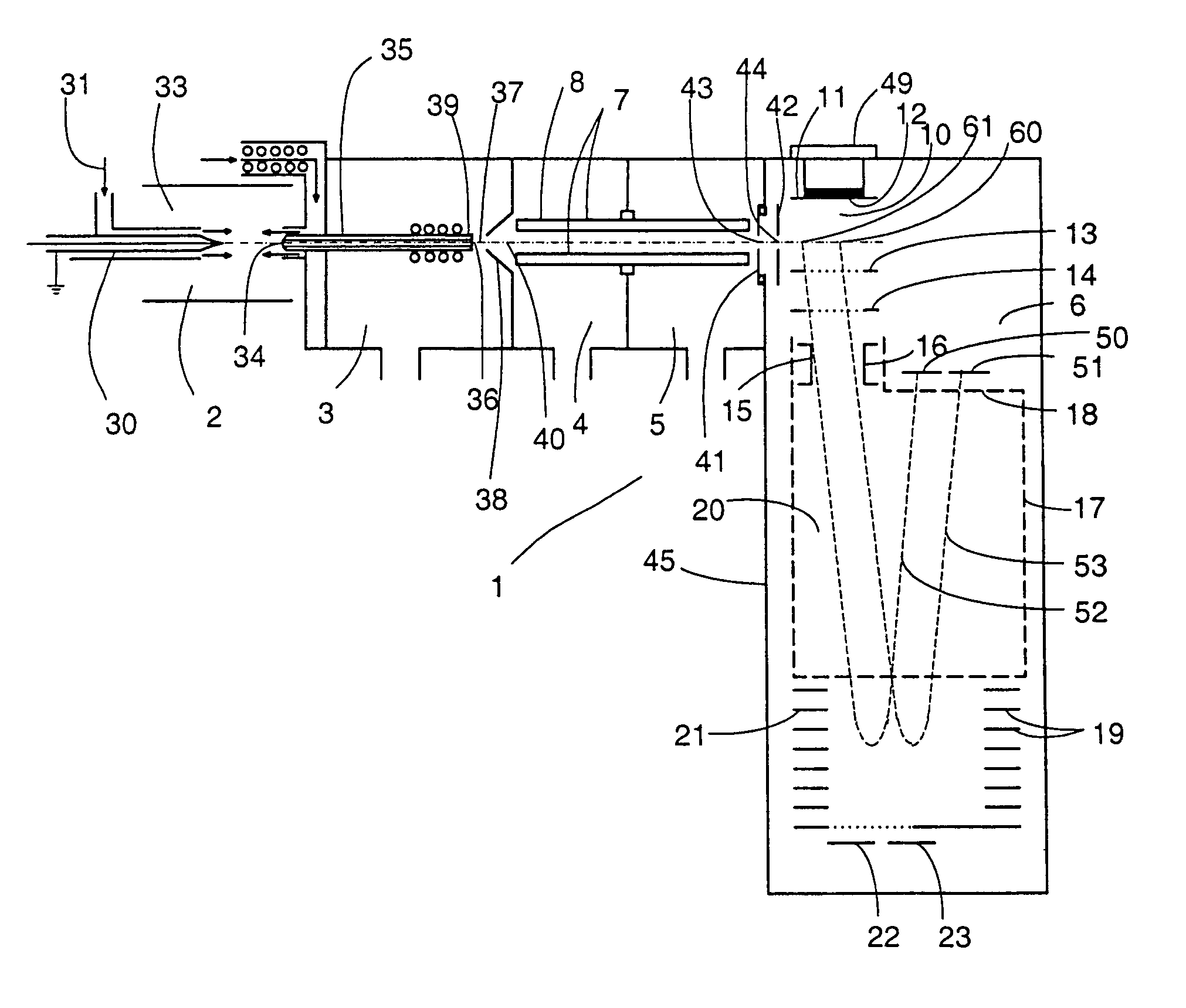
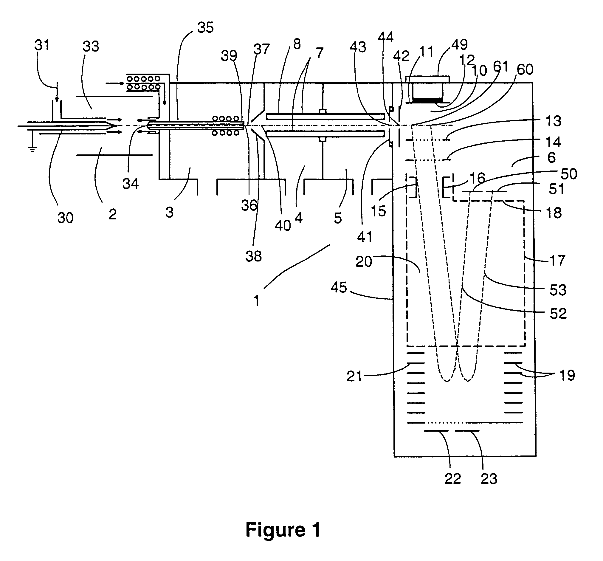
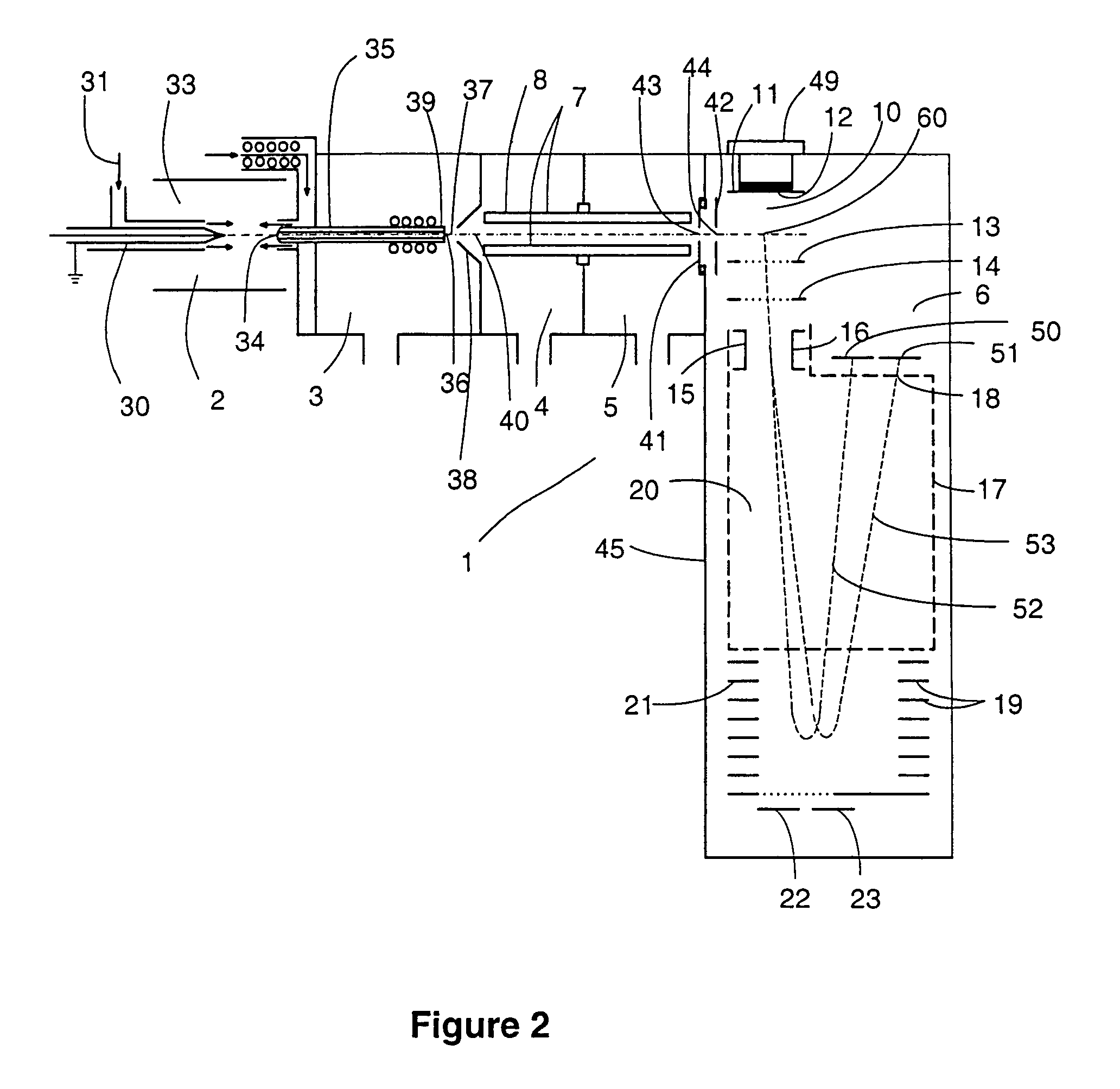
[0052]Time-of-Flight (TOF) mass analyzers that incorporate a linear or an orthogonal pulsing region as a means for pulsing ion bunches into the ToF tube are well known to those skilled in the art. Orthogonal pulsing Time-of-flight (O-TOF) mass analyzers are typically configured with the ion source located external to the TOF pulsing region. The primary beam of ions exiting an ion source is directed into the pulsing region of the TOF with a trajectory oriented substantially orthogonal to the axis of the Time-of-flight tube drift region. Several types of ion sources can be interfaced with orthogonal pulsing Time-of-flight mass analyzers. These include but are not limited to Electron Ionization (EI), Chemical ionization (CI), Photon and Multiphoton Ionization, Fast Atom Bombardment (FAB), Laser Desorption (LD), Matrix Assisted Laser Desorption (MALDI), Thermospray (TS), sources as well as Atmospheric Pressure Ion (API) sources including Electrospray (ES), Atmospheric Pressure Chemical ...


PUM


Abstract

A particle detection system is configured and operated as two or more separate and completely independent detection systems. The detection systems may be of the same or different design, may be operated in the same or different modes, and may be operated with the same or different operating parameters. Each detection system may record signals simultaneously, or alternately; the measurements obtained from each of the detection systems may either be combined into a single unified data set, or recorded separately. Means are provided to direct particles to impinge on one of the detectors or any of the other detectors. Alternatively, a population of particles can be dispersed in a manner that allows a population of particles to be distributed among two or more detectors simultaneously. The implementation of completely independent detection systems, for example, in a Time-of-Flight mass spectrometer, allows the design and operation of each detection system to be optimized independently, while being employed simultaneously. The flexibility afforded by the apparatus and methods in the invention allows signals to be recorded with enhanced signal dynamic range, signal-to-noise, and / or temporal resolution, relative to other presently available detection systems.

Description

[0001]This application is a continuation of U.S. Ser. No. 10 / 155,191, Filed May 24, 2002 now U.S. Pat. No. 7,265,346, which itself claims the priority of provisional patent application Ser. No. 60 / 293,782, Filed May 25, 2001, the contents of both of the prior applications being incorporated herein by reference.FIELD OF THE INVENTION[0002]The present invention relates to the field of particle detection systems. Specifically, the present invention provides methods and apparatus for the detection and recording of intensity signals from a flux of incident particles with improved performance.BACKGROUND OF THE INVENTION[0003]Various kinds of detectors and signal recording technologies are employed in many different kinds of instruments for the detection and measurement of particles such as photons, electrons, ions, and neutral particles. For the purposes of the present invention disclosure, the present invention will be described with respect to the specific application as a detection sys...

Claims


Application Information

Patent Timeline
Patent Type & Authority Patents(United States)
IPC IPC(8): H01J49/06H01J49/16H01J49/40
CPCH01J49/401H01J49/025
Inventor WHITEHOUSE, CRAIG M.WELKIE, DAVID G.
Owner PERKINELMER HEALTH SCIENCES INC
Why Eureka
Try Eureka