Optical coherence tomography imaging system and method

a coherence tomography and optical coherence technology, applied in the field of new oct imaging systems, can solve the problems of limiting the real-time imaging speed of conventional oct systems, recalibration process, and drawbacks of swept laser based oct systems, so as to improve signal quality, improve oct imaging quality, and reduce the amount of data points

Active Publication Date: 2011-05-03
THORLABS INC
View PDF22 Cites 78 Cited by
  • Summary
  • Abstract
  • Description
  • Claims
  • Application Information

AI Technical Summary

Benefits of technology

[0002]This application relates to a new OCT imaging system and methods for improving the efficiency, speed, and quality of the acquisition, generating, and display of one dimensional or multi-dimensional OCT images.
[0006]Also disclosed are methods to improve OCT imaging quality: By over-sampling the OCT signals and frequency clock signals, and applying various algorithms to digitally process the over-sampled data points to improve signal quality and reduce the amount of data points needed to be transferred to computer memory, the OCT image quality can be significantly improved without compromising the imaging speed.

Problems solved by technology

However, a swept laser based OCT system has some drawbacks.
First, because the scanning wavelength of a high-speed tunable laser is usually not linear in optical frequency space, recorded OCT data points must be recalibrated from time domain to equally spaced data points in optical frequency.
This recalibration process can be time-consuming because it must be performed for each scan of the laser corresponding to one axial line (A-scan) in the constructed OCT image, which greatly limits the real-time imaging speed of conventional OCT systems.
Second, in the dynamic process of actively tuning the laser frequency, the laser undergoes significant changes in cavity conditions (i.e., cavity length, average mode number, or number of modes), which cause both intensity and phase instabilities and noise in the laser output.
The intensity noise and phase noise degrade detection sensitivity and final image quality.
This is a problem that cannot be completely resolved by the balanced detection method.

Method used


Image

  • Optical coherence tomography imaging system and method
  • Optical coherence tomography imaging system and method
  • Optical coherence tomography imaging system and method

Examples


Embodiment Construction

m;

[0017]FIGS. 7a and 7b illustrate exemplary embodiments of a frequency clock module of an optical imaging system;

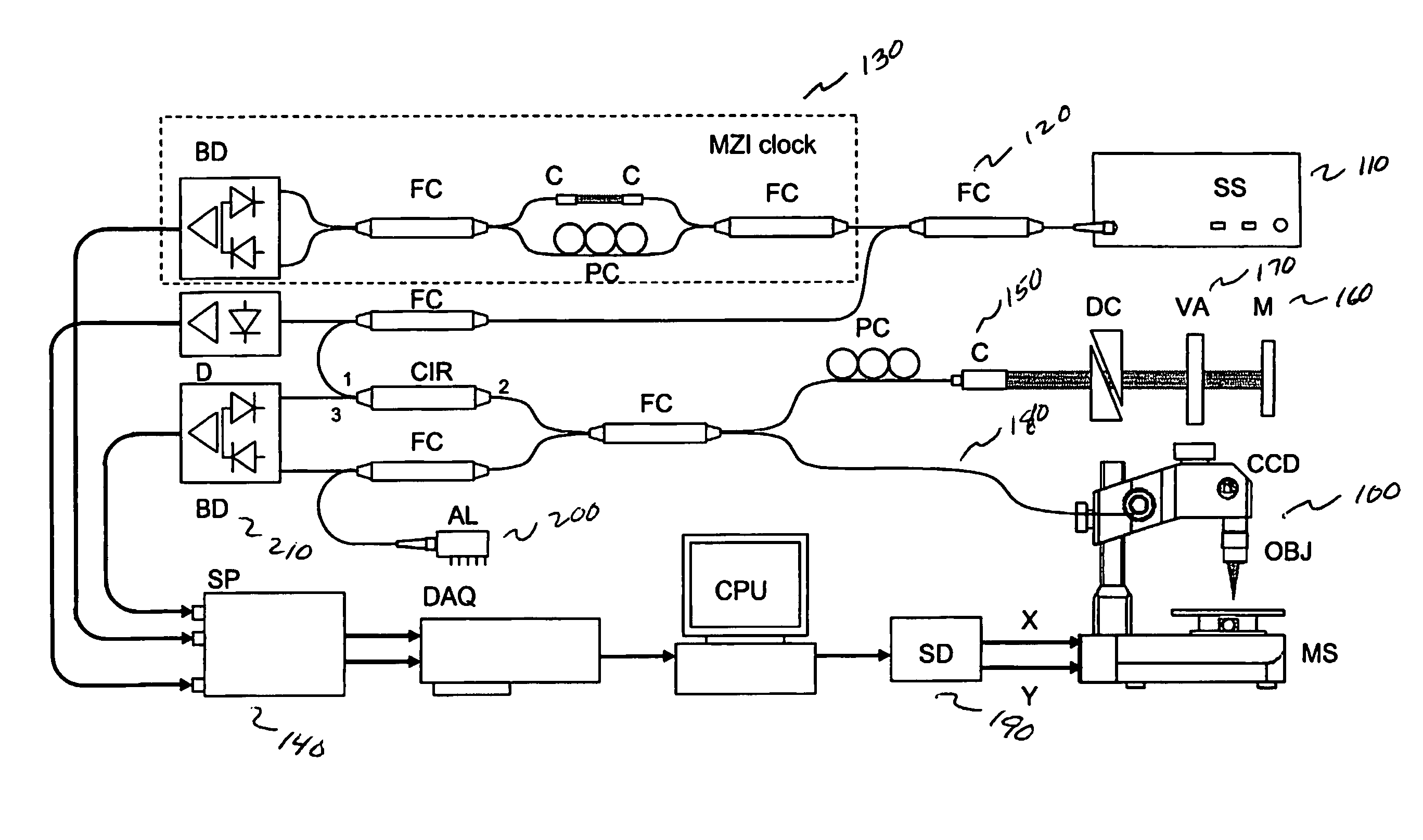
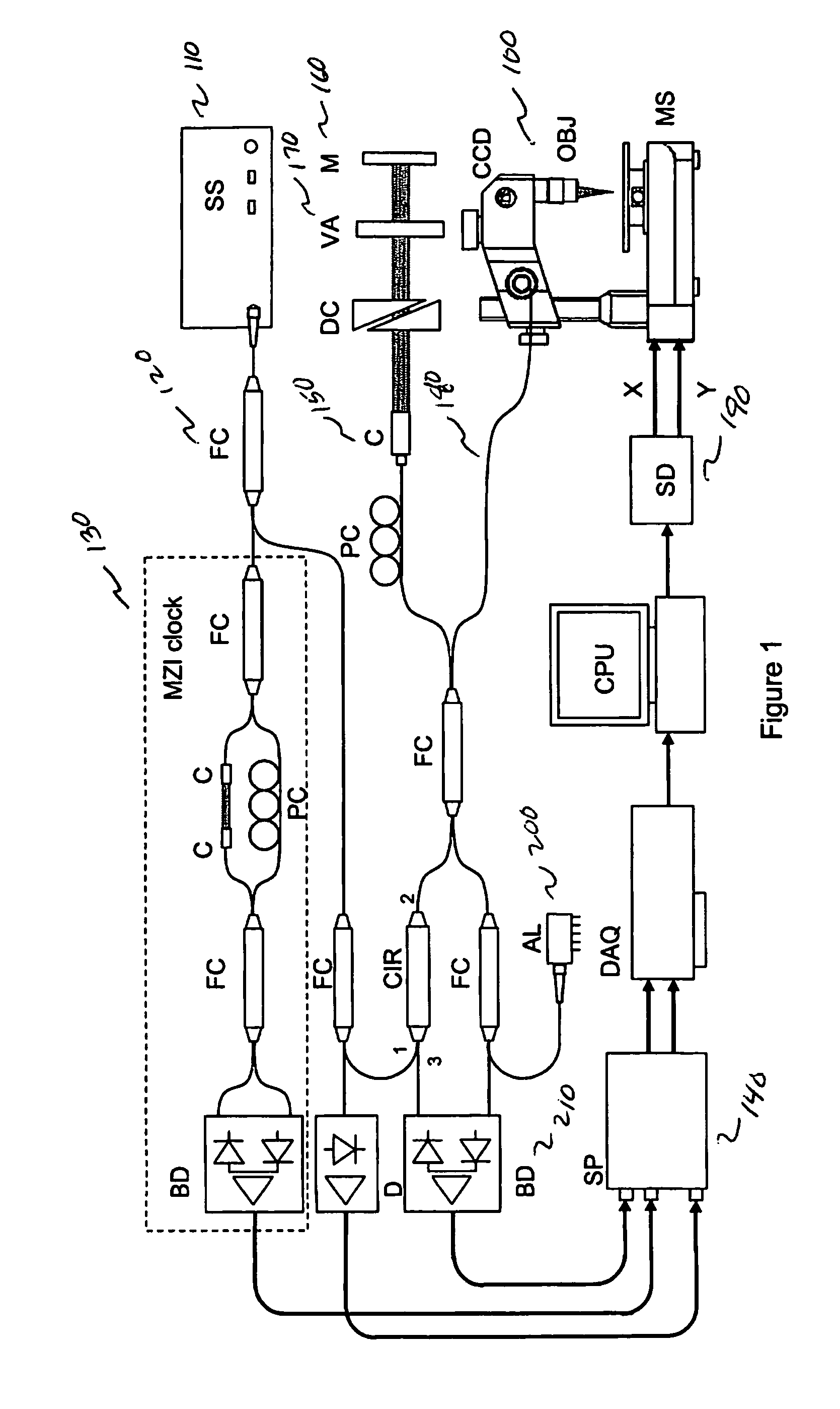
[0018]FIGS. 8-12 each illustrate exemplary embodiments of optical imaging systems according to the principles of the invention;

[0019]FIG. 13 illustrates, in block diagram form, an exemplary method realized in accordance with the principles of the present invention;

[0020]FIGS. 14-16 each illustrate exemplary embodiments of multiple-channel optical imaging systems according to the principles of the invention.

DETAILED DESCRIPTION OF THE PREFERRED EMBODIMENTS

[0021]This disclosure describes the best mode or modes of practicing the invention as presently contemplated. This description is not intended to be understood in a limiting sense, but provides an example of the invention presented solely for illustrative purposes by reference to the accompanying drawings to advise one of ordinary skill in the art of the advantages and construction of the invention. In the various views ...


PUM


Abstract

An optical imaging system includes an optical radiation source (410, 510), a frequency clock module outputting frequency clock signals (420), an optical interferometer (430), a data acquisition (DAQ) device (440) triggered by the frequency clock signals, and a computer (450) to perform multi-dimensional optical imaging of the samples. The frequency clock signals are processed by software or hardware to produce a record containing frequency-time relationship of the optical radiation source (410, 510) to trigger the sampling process of the DAQ device (440). The system may employ over-sampling and various digital signal processing methods to improve image quality. The system further includes multiple stages of routers (1418, 1425) connecting the light source (1410) with a plurality of interferometers (1420a-1420n) and a DAQ system (1450) triggered by frequency clock signals to perform high-speed multi-channel optical imaging of samples.

Description

[0001]This application claims the benefit under 35 U.S.C. §119(e) from U.S. Application 60 / 885,874, filed Jan. 19, 2007, the contents of which are incorporated herein by reference.INTRODUCTION[0002]This application relates to a new OCT imaging system and methods for improving the efficiency, speed, and quality of the acquisition, generating, and display of one dimensional or multi-dimensional OCT images.[0003]Optical coherence tomography (OCT) is an emerging imaging technology based on low-coherence interferometry that enables non-invasive, cross-sectional imaging of a sample with micrometer scale resolution. It has been demonstrated that Fourier domain OCT (FD-OCT) techniques can significantly improve the sensitivity and imaging speed of an OCT system. In FD-OCT systems, the interference fringe signals are recorded as a function of optical frequency at high-speed using a broadband light source and a spectrometer pair, or a frequency swept laser source and a detector pair. After ana...

Claims


Application Information

Patent Timeline
Patent Type & Authority Patents(United States)
IPC IPC(8): G01B11/02
CPCG01B9/02004G01B9/02027G01B9/02069G01B9/02083G01B9/02091G01B2290/45
Inventor JIANG, JAMES Y.BARRY, SCOTTCABLE, ALEX E.
Owner THORLABS INC
Why Eureka
Try Eureka