
Power amplifier linearization using RF feedback

a technology of linearization and power amplifiers, applied in the direction of amplifier combinations, amplifier modifications to reduce non-linear distortion, line-transmission details, etc., can solve the problems of inconvenient operation, inconvenient use, and inability to adjust the adaptive digital predistortion system, etc., to achieve the same good linearity and improve efficiency

Inactive Publication Date: 2011-05-10
RPX CORP
View PDF4 Cites 5 Cited by
  • Summary
  • Abstract
  • Description
  • Claims
  • Application Information

AI Technical Summary

Benefits of technology

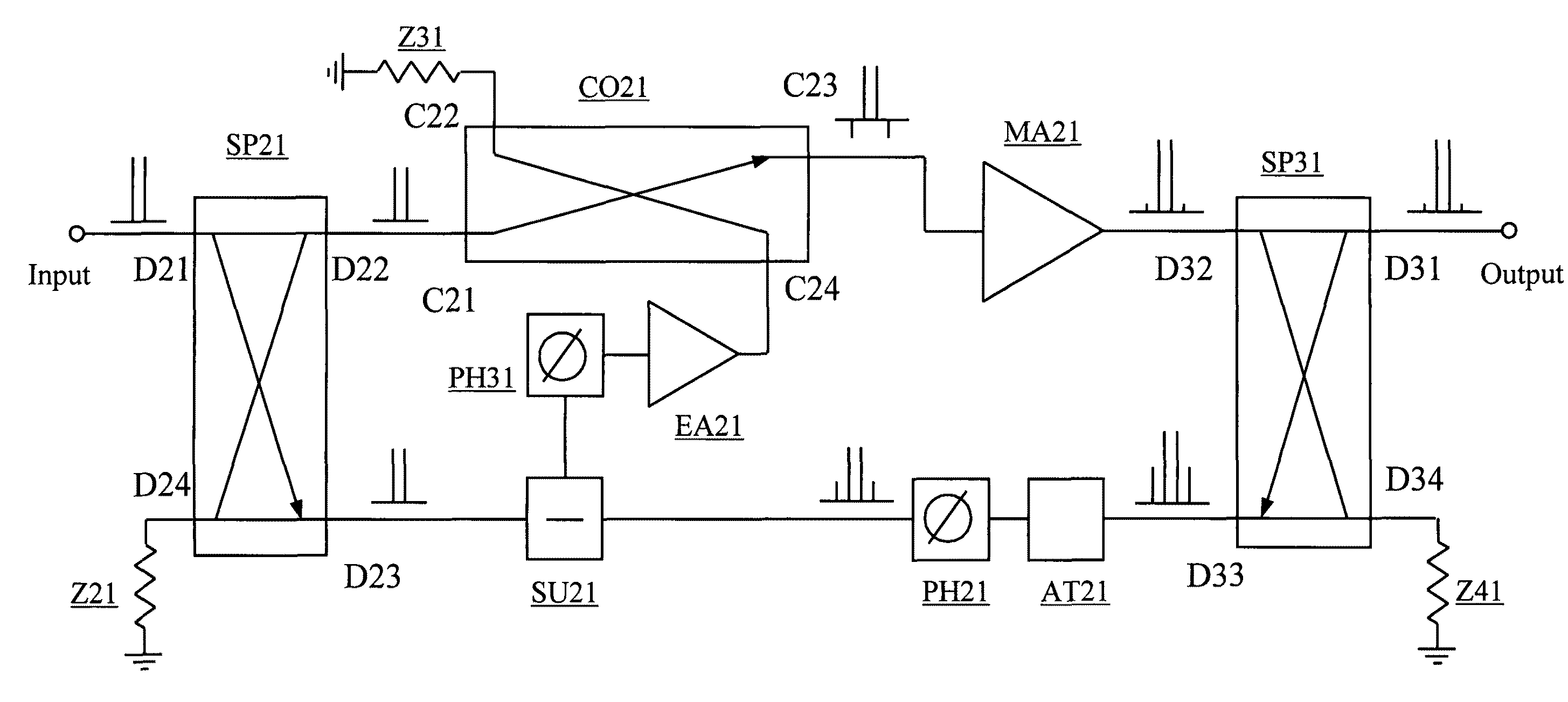
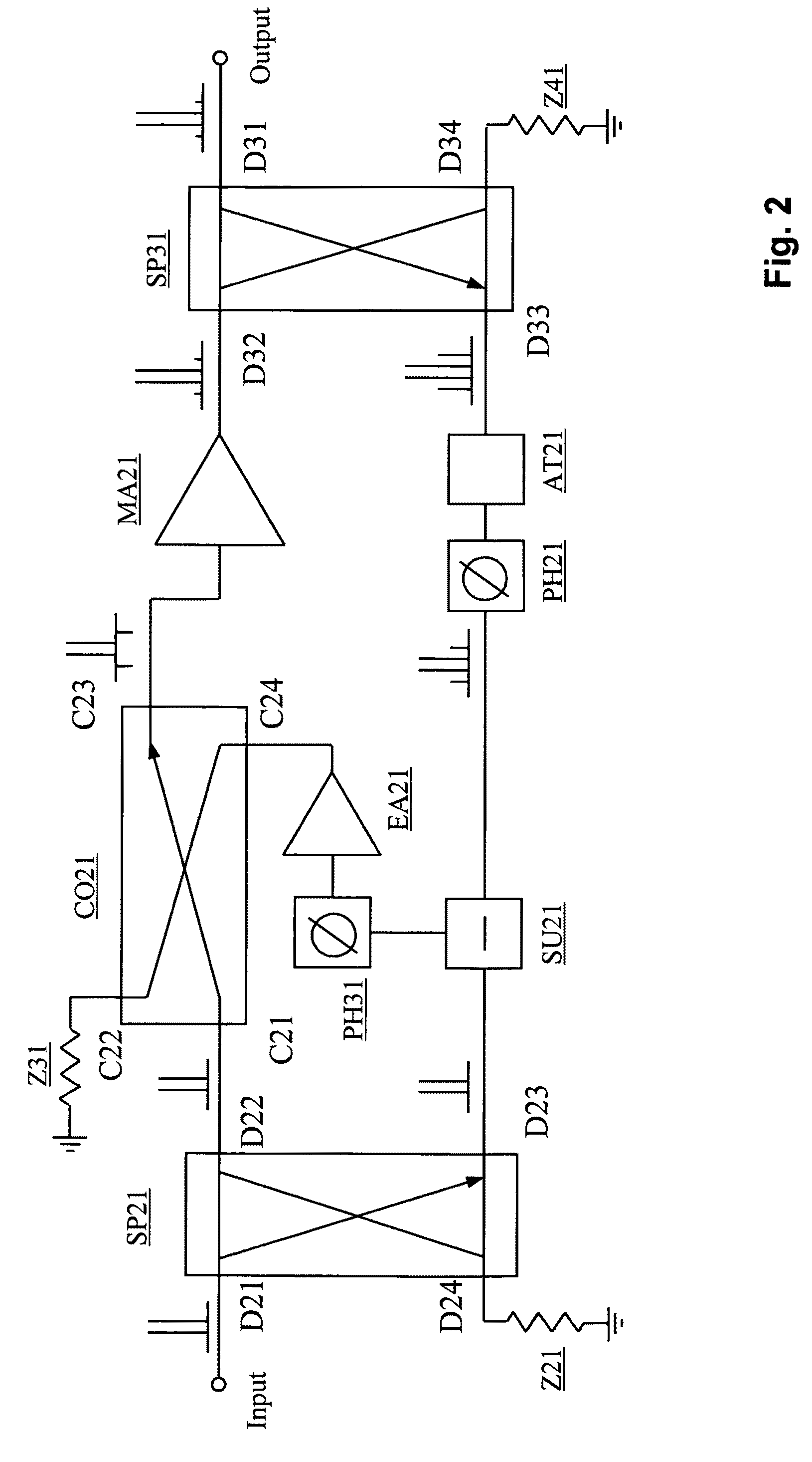
The present invention provides a power amplifier with improved efficiency while maintaining good linearity. This is achieved by using a quadrature hybrid combiner with a main port and a 90° phase shift port connected to an input of a main amplifier. The other quadrature hybrid has a main port connected to the output of the power amplifier. The quadrature hybrids have the advantage of lacking reflection waves at the main port, resulting in a higher input voltage standing wave ratio. The invention provides higher efficiency for the same linearity as common feedforward methods. The term ‘comprising’ refers to the inclusion of components A and B in a device, while the term ‘coupled’ refers to the connection of components A and B through a path that may include other devices or means.

Problems solved by technology

However, there is a tradeoff between efficiency and linearity with improvement in one coming at the expense of another.
However, a substantial linearity improvement comes without incurring a bandwidth limitation when the power amplifier can be considered memoryless, which is not the case for wideband telecommunication standards like CDMA200 or WCDMA.
As said, the complexity of the adaptive digital predistortion system is a serious drawback because it is implemented with considerable computing power of a digital signal processor.
But as soon as the number of power amplifiers in a base station increases, as it is the case in distributed and active antenna applications, this effort gets prohibitively expensive: e.g. in an active antenna for macro-base-station applications the number of transceiver elements is about eight to ten.
To install an individual Digital PreDistortion-Field Programmable Gate Array DPD-FPGA, an individual sampling receiver and a complex duplex filter in each antenna element is prohibitive in terms of form factor, cost and weight.
Existing feedforward power amplifiers which improve linearity already exist, but those are of inherently low efficiency.
However, efficiency in this feedforward system is very low because the power consumption of the error amplifier is significant in order to obtain the required error signal at the output.
In addition, the phase shifter and attenuator at the output path make a significant contribution to the overall system power loss.

Method used


Image

  • Power amplifier linearization using RF feedback
  • Power amplifier linearization using RF feedback
  • Power amplifier linearization using RF feedback

Examples


Embodiment Construction

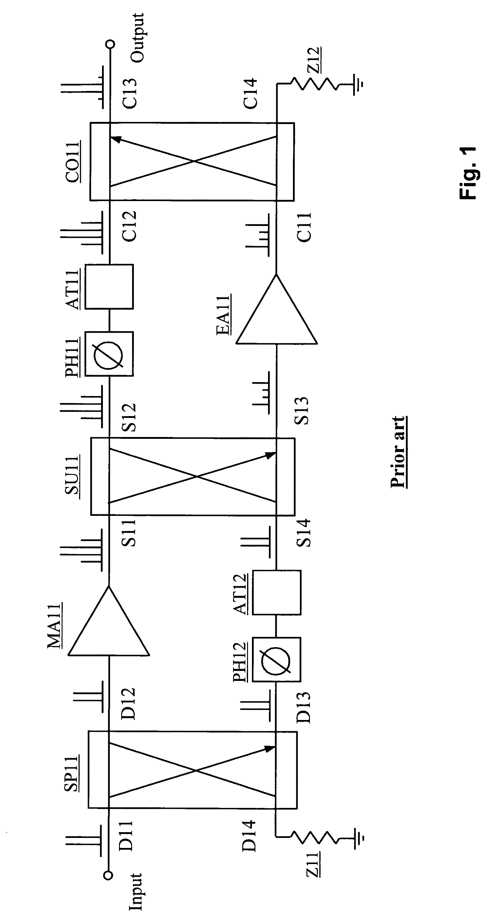
[0024]The feedforward power amplifier shown at FIG. 1 is known from the prior art and includes a main amplifier MA11, a quadrature hybrid splitter SP11, a quadrature hybrid subtracter SU11, quadrature hybrid combiner CO11, two phase shifters PH11 and PH12, two attenuators AT11 and AT12, and error amplifier EA11.

[0025]The operation of this feedforward linearization circuit is based on the subtraction of two equal signals with subsequent cancellation of the error signal in the amplifier output spectrum. Its operation principle can be demonstrated by the two-tone test spectra at various points of the block diagram. The input signal D11 is split to form the two identical parts D12 and D13, although in a common case the ratio used in the splitting process SP11 does not need to be equal. Then, a portion S11 of the main amplifier output signal coupled by the coupler-subtracter SU11 is subtracted from a time-delayed and opposite phase portion S14 of the original signal to remain an error si...


PUM


Abstract

The power amplifier mainly includes a main amplifier, two splitters, one combiner, one subtracter, two phase shifters, one attenuator and one error amplifier. The splitters, subtracter and combiner are designed in the form of 90-degree or quadrature hybrid couplers. A quadrature hybrid can be implemented with any lumped or transmission-line elements and has an important advantage compared to the in-phase splitter that at equal values of reflection coefficients from loads connected to the in phase and 90° phase shift terminals, the reflection wave is lacking at the main input terminal and, consequently, the input voltage standing wave ratio of a quadrature hybrid does not depend on the equal load mismatch level.

Description

CROSS REFERENCE TO RELATED APPLICATIONS[0001]The present application claims priority to and incorporates by reference the entire contents of European Patent Application No. 08290846.8 filed on Sep. 9, 2008.BACKGROUND OF THE INVENTION[0002]The present invention relates to a power amplifier having an input connected to a main port of a quadrature hybrid splitter, said quadrature hybrid splitter having an in-phase port coupled to an output of said power amplifier through a main amplifier and another quadrature hybrid, said quadrature hybrid splitter further having a 90° phase shift port also coupled of said other quadrature hybrid.[0003]Such a power amplifier PA is already known in communication systems, such as Global System for Mobile communications / Enhanced Data rates for GSM Evolution GSM / EDGE, code-division multiple-access CDMA2000, wide-band code-division multiple-access W-CDMA and Long Term Evolution LTE, where it is required to operate with high efficiency and high linearity si...

Claims


Application Information

Patent Timeline
Patent Type & Authority Patents(United States)
IPC IPC(8): H03F3/68
CPCH03F1/345H03F1/32H03F3/24H03F3/245H04B1/207H04B1/52H04B1/69H04B1/692H04B3/03
Inventor GREBENNIKOV, ANDREIPIVIT, FLORIAN
Owner RPX CORP
Learn More