
Hydrogen separation process

a technology of hydrogen separation membrane and hydrogen, which is applied in the direction of inorganic chemistry, climate sustainability, synthetic resin layered products, etc., can solve the problems of limiting the system, operating at about 38° c, and loss of thermal efficiency

Inactive Publication Date: 2011-05-24
ELTRON RES INC
View PDF20 Cites 8 Cited by
  • Summary
  • Abstract
  • Description
  • Claims
  • Application Information

AI Technical Summary

Problems solved by technology

One of the major disadvantages of this type system is that it operates at about 38° C.
This entails a loss of thermal efficiency because the entire gas stream must be cooled prior to introduction into the pressure swing adsorption beds.
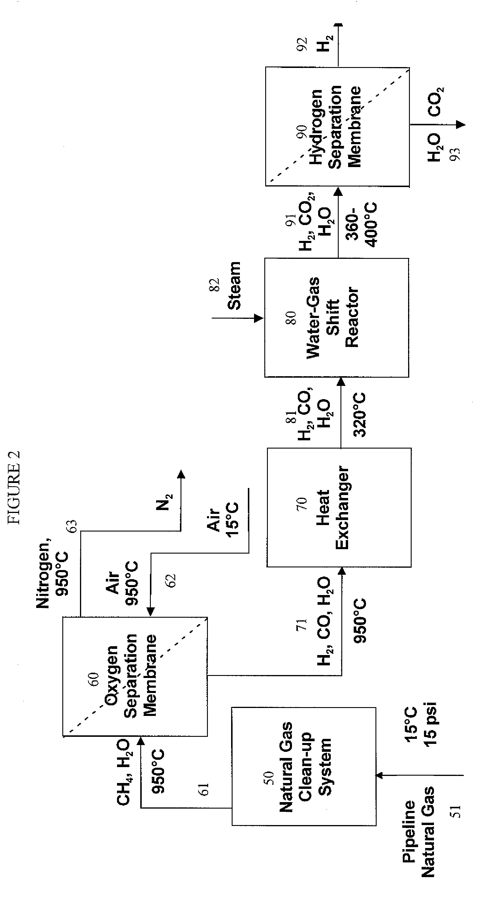
Another disadvantage of PSA is that low raffinate pressure essentially limits the system to a single stage of water gas shift, WGS, which is often used to convert CO to CO2 and to produce additional hydrogen from synthesis gas streams.
PSAs are also undesirable compared to filters and membranes, due to mechanical complexity, which leads to higher capital and operating expenditures and, potentially, increased downtime.

Method used


Image

  • Hydrogen separation process
  • Hydrogen separation process
  • Hydrogen separation process

Examples


example 1

Membrane Pretreatment

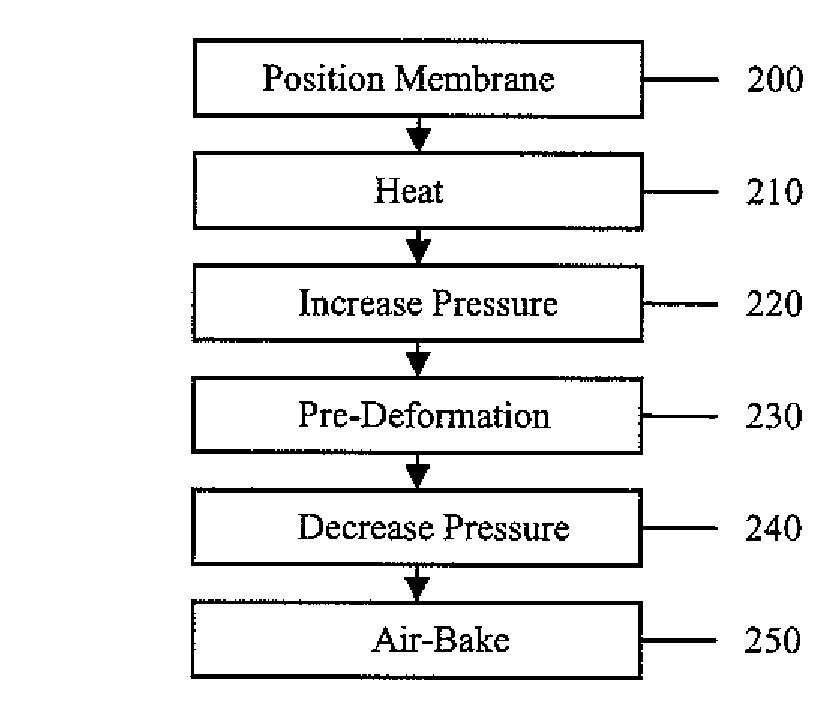
[0107]Prior to use in a hydrogen separation process, the membranes to be used are pretreated. Although applicant does not wish to be bound by theory, it is believed this pretreatment process minimizes the mechanical stress the membrane undergoes under actual operating conditions and improves the lifetime of the membrane and the performance of the membrane. Without this pretreatment procedure, the membrane will break at about 5 psig to 10 psig of outlet hydrogen pressure. The following description illustrates one specific example of the pretreatment procedure. Other specific useful process parameters, such as different reaction times, temperatures, membrane materials, pressures, and gases, are easily determined by one of ordinary skill in the art using the description provided herein without undue experimentation.

[0108]A vanadium membrane having a ⅞″ diameter was punched out from a sheet of V (about 130 microns thick, obtained from Aldrich) and cleaned with solve...

example 2

Integrated WGS and HTM

[0115]Two lab-scale IWGSMR modules, respectively accommodating one and two hydrogen transport membranes, were designed, fabricated and assembled. The reactor modules were fabricated from stainless steel flanges of 2.75″ diameter. The membrane fitting into the 2.75″ flanges have a diameter of 1.89″. The copper gaskets used had an inner diameter of 1.45″ providing an active membrane surface area of 10.6 square centimeters (1.65 square inch) for each membrane. It was found that commercial Cr / Fe oxide-based water-gas shift catalyst (C12-4-02 from Süd-Chemie) was compatible with the hydrogen transport membranes constituted with surface Pd catalysts when the fresh commercial WGS catalyst was pre-treated in a hydrogen-stream (1:5 molar ratio) for one week to remove residual sulfate. The Cr / Fe oxide catalyst was packed in close proximity to the membrane surface without touching the membrane surface.

[0116]Optimized operating parameters, including composition and gas hou...

example 3

Long-Term Separation of H2 from WGS Gas with HTM

[0121]A composite HTM was tested at ambient pressure with a full mixture of water-gas shift gas containing 41.4% H2, 3.3% CO, 17.8% CO2, 37.3% steam and balance of inert gases in volume at 340° C. The feed side reactor compartment was packed with low-temperature water-gas shift catalyst (Cu / ZnO obtained from Süd Chemie) as the guard bed. FIG. 9 is a plot of hydrogen flux through a composite HTM as a function of time. As shown in FIG. 9, the membrane displayed an initial hydrogen flux of approximately 14 mL·min−1·cm−2 (STP), corresponding to an apparent hydrogen permeability of 1.4×10⁻⁷ mol·m−1·s−1·Pa−0.5. After four months (approximately 2,800 hrs) of continuous operation in the full water-gas shift mixture, the composite membrane maintained about 10 mL·min−1·cm2 (STP) of hydrogen flux and an apparent permeability of 1.0×10⁻⁷ mol·m−1·s−1·Pa−0.5, which is better than unalloyed palladium.


PUM

PropertyMeasurementUnit
temperatureaaaaaaaaaa
pressureaaaaaaaaaa
thicknessaaaaaaaaaa

Abstract

A method for separating a hydrogen-rich product stream from a feed stream comprising hydrogen and at least one carbon-containing gas, comprising feeding the feed stream, at an inlet pressure greater than atmospheric pressure and a temperature greater than 200° C., to a hydrogen separation membrane system comprising a membrane that is selectively permeable to hydrogen, and producing a hydrogen-rich permeate product stream on the permeate side of the membrane and a carbon dioxide-rich product raffinate stream on the raffinate side of the membrane. A method for separating a hydrogen-rich product stream from a feed stream comprising hydrogen and at least one carbon-containing gas, comprising feeding the feed stream, at an inlet pressure greater than atmospheric pressure and a temperature greater than 200° C., to an integrated water gas shift / hydrogen separation membrane system wherein the hydrogen separation membrane system comprises a membrane that is selectively permeable to hydrogen, and producing a hydrogen-rich permeate product stream on the permeate side of the membrane and a carbon dioxide-rich product raffinate stream on the raffinate side of the membrane. A method for pretreating a membrane, comprising: heating the membrane to a desired operating temperature and desired feed pressure in a flow of inert gas for a sufficient time to cause the membrane to mechanically deform; decreasing the feed pressure to approximately ambient pressure; and optionally, flowing an oxidizing agent across the membrane before, during, or after deformation of the membrane. A method of supporting a hydrogen separation membrane system comprising selecting a hydrogen separation membrane system comprising one or more catalyst outer layers deposited on a hydrogen transport membrane layer and sealing the hydrogen separation membrane system to a porous support.

Description

CROSS-REFERENCE TO RELATED APPLICATIONS[0001]This application claims benefit from provisional application Ser. No. 60 / 765,524 filed Feb. 6, 2006, which is hereby incorporated herein by reference in its entirety for all purposes as if reproduced in full below.STATEMENT REGARDING FEDERALLY SPONSORED RESEARCH OR DEVELOPMENT[0002]The U.S. Government has a paid-up license in this invention and the right in limited circumstances to require the patent owner to license others on reasonable terms as provided for by the terms of DOE Contracts No. DE-FC26-00NT40762, DE-FC26-05NT42469, DE-FG02-04ER83934, DE-FG02-04ER83935, and DE-FG02-05ER84199 awarded by the Department of Energy.BACKGROUND OF THE INVENTION[0003]1. Field of the Invention[0004]This disclosure relates to a method of separating hydrogen from a hydrogen-containing stream using a hydrogen separation membrane system. More particularly, this disclosure relates to a method of separating a stream consisting essentially of hydrogen from ...

Claims


Application Information

Patent Timeline
Patent Type & Authority Patents(United States)
IPC IPC(8): B01D53/22B29C48/76
CPCB01D53/226B01D53/229C01B3/503C01B3/505B01D2257/108C01B2203/86C01B2203/041C01B2203/0465C01B2203/047C01B2203/0475C01B2203/0495C01B2203/0405Y02P30/00Y02P20/141
Inventor MUNDSCHAU, MICHAELXIE, XIAOBINGEVENSON, IV, CARLGRIMMER, PAULWRIGHT, HAROLD
Owner ELTRON RES INC
Learn More