Extending storage time of removed plasma chamber components prior to cleaning thereof

Active Publication Date: 2011-07-12
LAM RES CORP
View PDF16 Cites 3 Cited by
  • Summary
  • Abstract
  • Description
  • Claims
  • Application Information

AI Technical Summary

Benefits of technology

A method of extending storage time of a removed component of a plasma chamber prior to cleaning thereof comprises removing the component from the chamber, covering a thermal spray coating on the component while the surface is exposed to atmospheric air, and storing the component. The covering allows extended storage of the component until a cleaning process is performed by removing the covering and cleaning reaction by-products from the thermal spayed coating.

Problems solved by technology

Generally, replacement of such components is expensive, and component lifetime as measured by the total number of wafers processed before replacement is needed is typically the denominator in the cost determination.
Components with lifetimes that are considered low are therefore considered expensive and alternative solutions are generally sought.

Method used


Image

  • Extending storage time of removed plasma chamber components prior to cleaning thereof
  • Extending storage time of removed plasma chamber components prior to cleaning thereof
  • Extending storage time of removed plasma chamber components prior to cleaning thereof

Examples


example 1

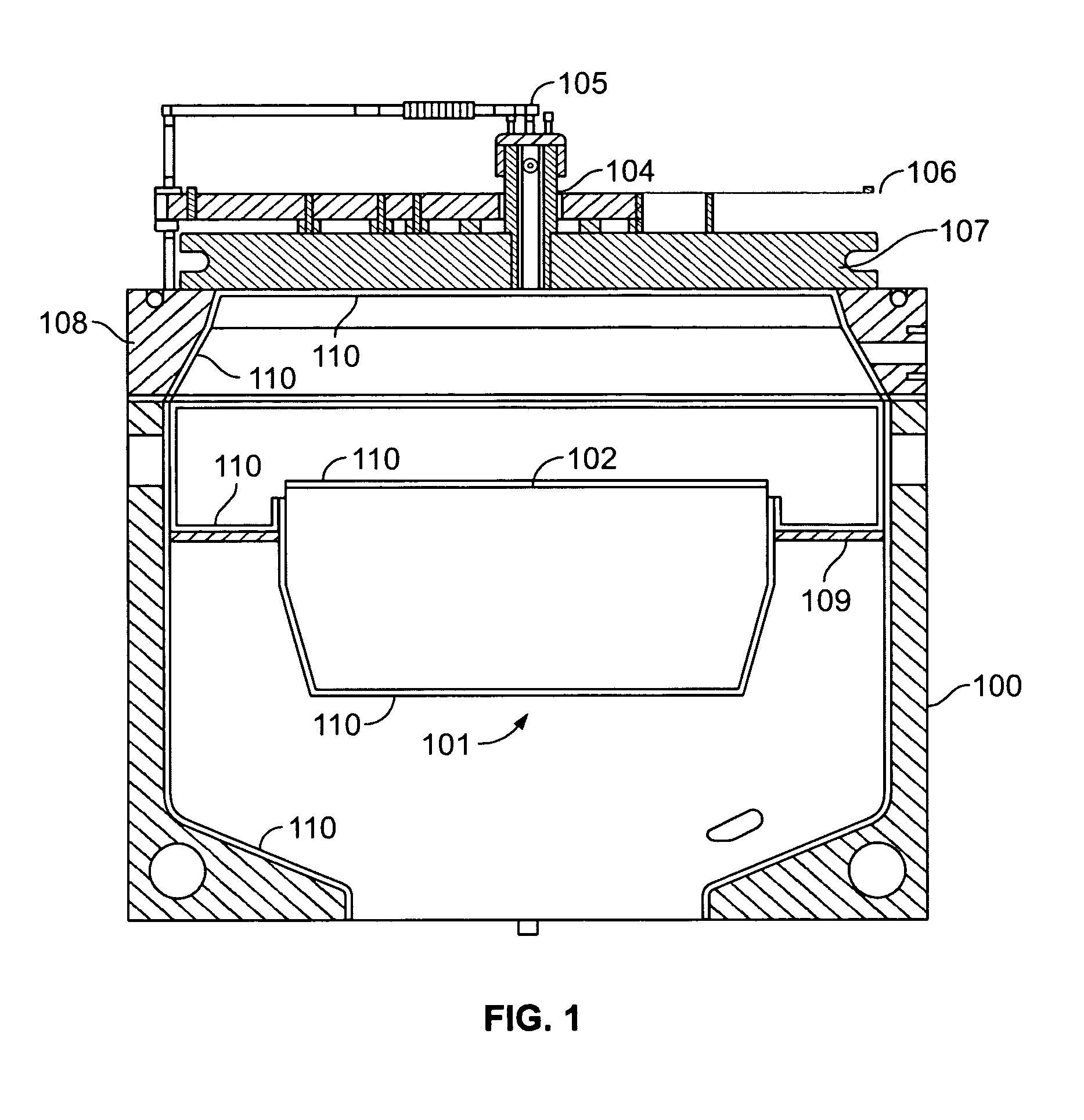
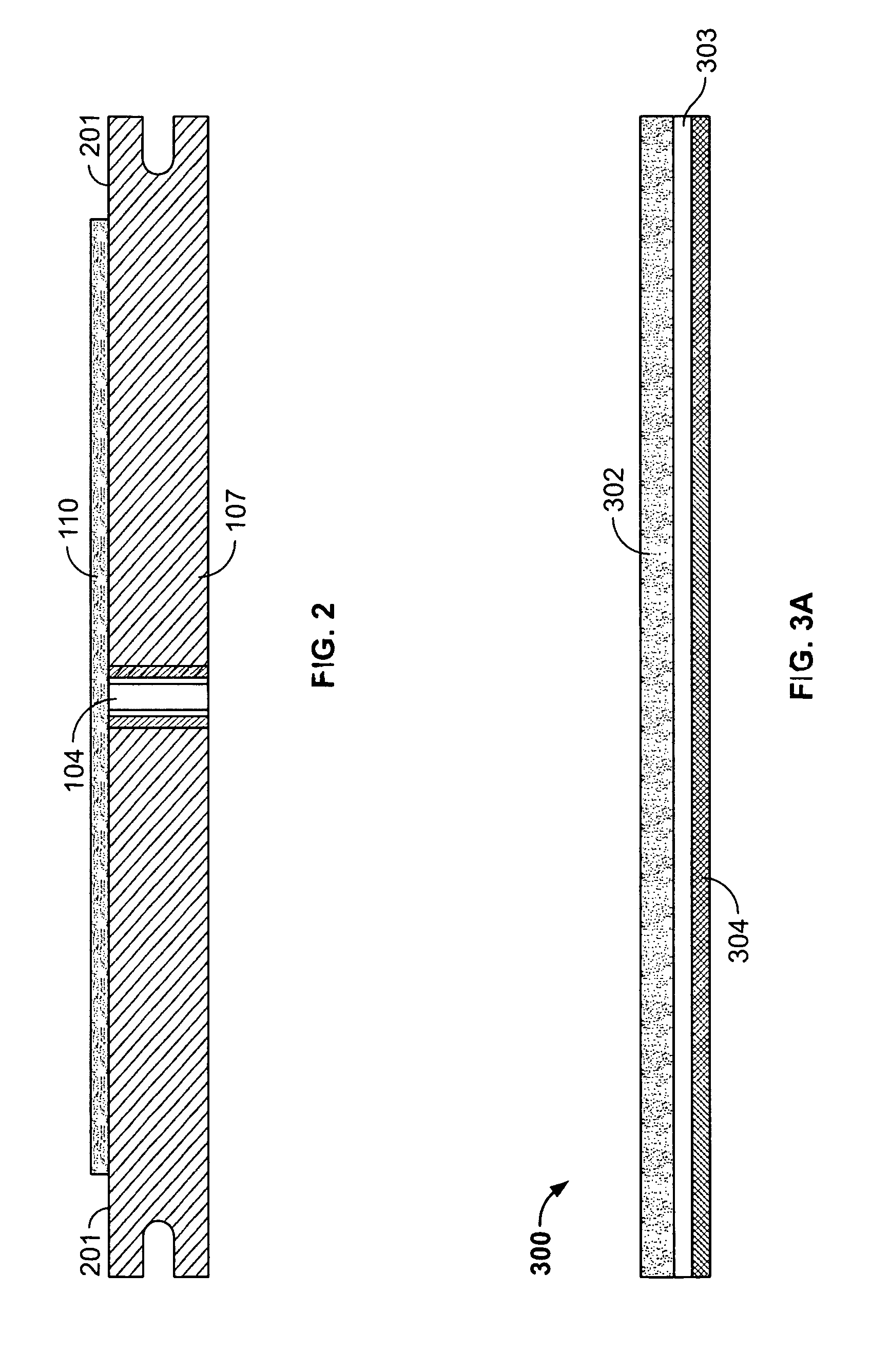
A schematic illustration of a Versys 2300™ conductor etch plasma chamber as shown in FIG. 1 is available from Lam Research Corporation in Fremont, Calif. FIG. 2 shows the yttria coated ceramic window 107 coating-side up. The yttria coating 110 does not cover an outer ring-shaped area referred to as the ceramic sealing surface 201. FIG. 3 shows electroplating tape 300, such as 2 mil Green Polyester Tape, part # VGT 215 available from Advanced Paper Systems of San Jose, Calif., which consists of a substantially moisture impermeable material 302, an adhesive layer 303, and an adhesive cover layer 304.

Procedurally, the tape 300 is prepared by cutting, such that it is substantially the same dimension as the ceramic window 107. It is further prepared such that a ring-shaped adhesive portion 305 which is to be positioned over the ceramic sealing surface 201 is exposed by removing the adhesive cover in that region. A remaining disk-shaped adhesive portion which is to be positioned over the ...

example 2

Similar to example 1, the tape 300 is sized by cutting such that it is substantially the same dimension as the ceramic window 107. The tape 300 should be sized before the chamber is opened.

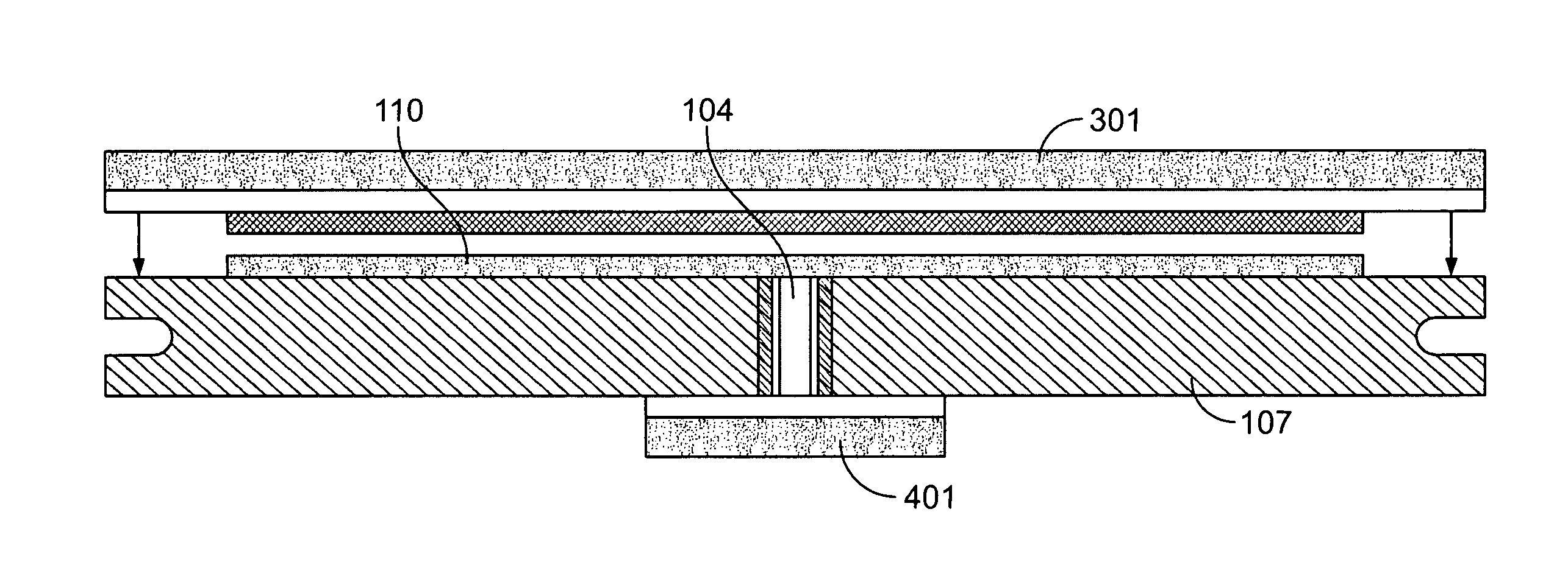
Immediately after opening the chamber 100 and removing the ceramic window 107, while it is still hot as a result of prior plasma etch operation of the reactor, additional electroplating tape 401 is used to seal the gas injector 104 from the ceramic side, shown in FIG. 4. The tape 401 is positioned such that substantially all of, the trapped air below the tape is removed.

With the window 107 positioned such that the yttria coating 110 is facing upwards, cleanroom wipes are used to cover the coating 110 without covering the ceramic sealing surface 201. An example of cleanroom wipes that can be used for this purpose are Cleanroom Polyester / Cellulose Blend Wipers, Spec-Wipe™ 3 available from VWR International, Inc., West Chester, Pa. Alternatively, a plastic sheet could be used. The annular section of ...


PUM

PropertyMeasurementUnit
Temperatureaaaaaaaaaa
Timeaaaaaaaaaa
Timeaaaaaaaaaa

Abstract

A method of extending storage time prior to cleaning a component of a plasma chamber is provided. The method comprises removing the component from the chamber, covering a thermal spray coating on the component while the surface is exposed to atmospheric air, storing the component, optionally removing the covering, and optionally wet cleaning reaction by-products from the thermal spray coating. Alternatively, instead of, or in addition to covering a thermal spray coating on the component, the component can be placed into a desiccator or dry-box.

Description

BACKGROUNDAs semiconductor technology evolves, decreasing transistor sizes call for an ever higher degree of accuracy, repeatability and cleanliness in wafer processes and process equipment. Fierce competition within the semiconductor industry calls for ever lower cost per processed wafer. All of these requirements apply generally to all of the processing equipment used in the fabrication sequence.Among the various types of equipment that exists for semiconductor processing is equipment that involves the use of plasmas, such as plasma etch, plasma-enhanced chemical vapor deposition (PECVD) and resist strip equipment. The types of equipment required for these processes include components which are located within the plasma chamber, and must function in that environment. The environment inside the plasma chamber may include exposure to the plasma and to etchant gasses, and materials used for such components are preferably adapted to withstand the environmental conditions in the chambe...

Claims


Application Information

Patent Timeline
IPC IPC(8): B08B17/04B08B3/08B08B3/04
CPCC23C16/4404
Inventor SHIH, HONGFU, QIANHUANG, TUOCHUANCASAES, RAPHAELOUTKA, DUANE
Owner LAM RES CORP
Why Eureka
Try Eureka