Digital thermal sensor test implementation without using main core voltage supply

a digital thermal sensor and main core technology, applied in heat measurement, liquid/fluent solid measurement, instruments, etc., can solve the problems of affecting the real-time guarantees of applications, most thermal management techniques are expensive and/or difficult to package, and the multi-core processors of today are often limited, so as to reduce or simple test/calibration sequence, and eliminate the effect of self-heating

Inactive Publication Date: 2011-09-27
IBM CORP
View PDF114 Cites 8 Cited by
  • Summary
  • Abstract
  • Description
  • Claims
  • Application Information

AI Technical Summary

Benefits of technology

[0006]The illustrative embodiments provide for test logic in an analog voltage domain in order to reduce or eliminate the need to enable core voltage supply and possibly encounter self-heating due to the leakage current used by the processor. Moving the test logic to the analog voltage domain provides advantages, such as eliminates the effect of self-heating during calibration, does not require the system to go through a power-on reset sequence to set up the core logic, provides a simpler test / calibration sequence, and requires less logic and a smaller footprint. In short, the illustrative embodiments improve calibration accuracy, reduce test time, reduce calibration complexity, and reduce area.

Problems solved by technology

Today's multi-core processors are frequently limited by thermal considerations.
Cooling may be expensive and / or difficult to package.
However, most thermal management techniques impact the real-time guarantees of an application.
However, within the current calibration processes with core voltage supply enabled, the processor consumes a significant amount of power due to leakage current and, in turn, the self-heating due to leakage current elevates the internal processor temperature.
This added variable makes the calibration process more difficult and also less accurate.

Method used


Image

  • Digital thermal sensor test implementation without using main core voltage supply
  • Digital thermal sensor test implementation without using main core voltage supply
  • Digital thermal sensor test implementation without using main core voltage supply

Examples


Embodiment Construction

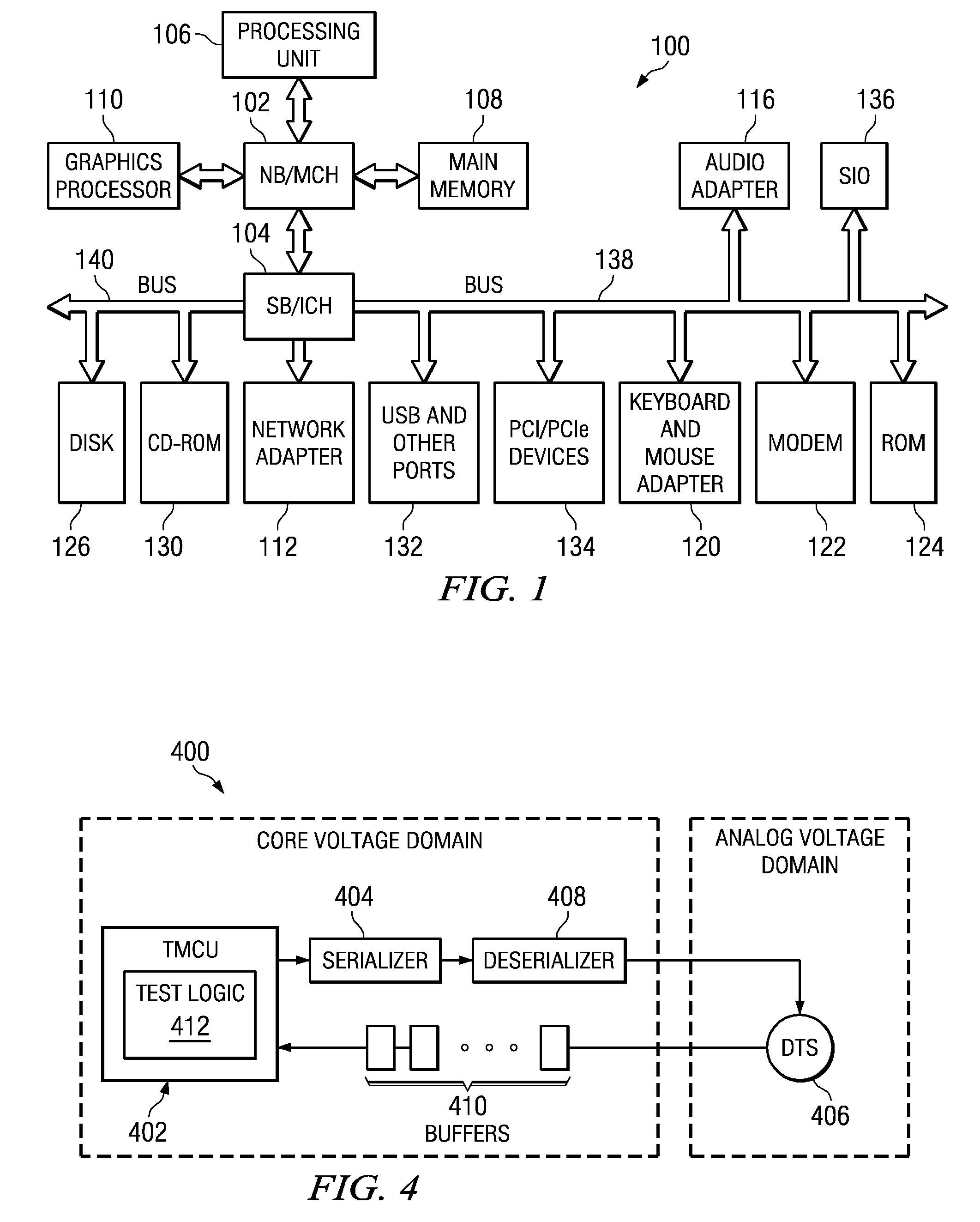
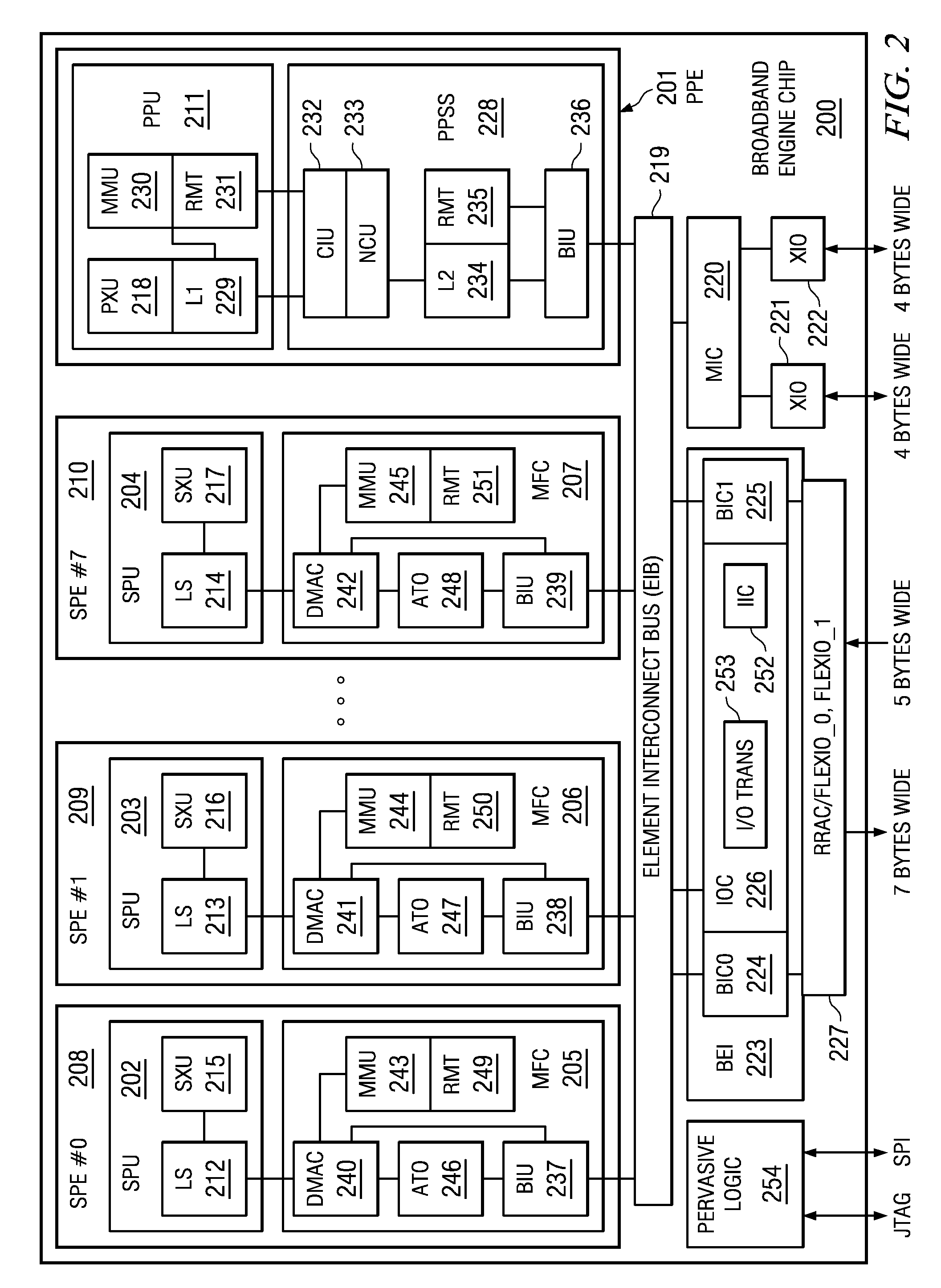
[0023]The illustrative embodiments provide for calibrating digital thermal sensors while consuming as little power as possible. Using as little power as possible during the calibration process may reduce or eliminate the effect of self-heating by the processor due to leakage current. While the illustrative embodiments are optimally used with a Cell Broadband Engine (BE) chip, the described features may be used with other data processing systems. Therefore, FIG. 1 is provided as a description of a general data processing system and FIG. 2 is provided as a description of a Cell BE chip. FIG. 1 is provided as an exemplary data processing system in which aspects of the illustrative embodiments may be implemented. Data processing system 100 is an example of a computer in which computer usable code or instructions implementing the processes for illustrative embodiments of the present invention may be located.

[0024]In the depicted example, data processing system 100 employs a hub architect...


PUM

PropertyMeasurementUnit
temperature thresholdaaaaaaaaaa
sizeaaaaaaaaaa
temperatureaaaaaaaaaa

Abstract

A method and apparatus are provided for calibrating digital thermal sensors. A processor chip with a plurality of digital thermal sensors receives an analog voltage. A test circuit coupled to the processor chip receives a clock signal and a register coupled to the test circuit outputs a value on each clock cycle to a digital thermal sensor in the plurality of digital thermal sensors. The digital thermal sensor transitions an output state in response to the value of the register received in the digital thermal sensor equaling a temperature threshold of the digital thermal sensor. The value of the register at the point of transition is used to calibrate the digital thermal sensor. An incrementer increments the value of the register on each clock cycle in response to the value of the register received in the digital thermal sensor failing to equal the temperature threshold of the digital thermal sensor.

Description

BACKGROUND[0001]1. Technical Field[0002]The present application relates generally to an improved data processing system and method. More specifically, the present application is directed to a digital thermal sensor test implementation that does not use main core voltage supply.[0003]2. Description of Related Art[0004]The first-generation heterogeneous Cell Broadband Engine™ (Cell BE) processor is a multi-core chip comprised of a 64-bit Power PC® processor core and eight single instruction multiple data (SIMD) synergistic processor cores, capable of massive floating point processing, optimized for compute-intensive workloads and broadband rich media applications. A high-speed memory controller and high-bandwidth bus interface are also integrated on-chip. Cell BE's breakthrough multi-core architecture and ultra high-speed communications capabilities deliver vastly improved, real-time response, in many cases ten times the performance of the latest PC processors. Cell BE is operating sy...

Claims


Application Information

Patent Timeline
Patent Type & Authority Patents(United States)
IPC IPC(8): G01C19/00H02H5/04G01K3/00
CPCG01K15/00G01K15/005
Inventor JOHNS, CHARLES R.RILEY, MACK W.SHAN, DAVID W.WANG, MICHAEL F.
Owner IBM CORP
Why Eureka
Try Eureka