Wafer level package structure, and sensor device obtained from the same package structure

a technology of package structure and sensor device, applied in the direction of turn-sensitive devices, semiconductor/solid-state device testing/measurement, instruments, etc., can solve the problem of increasing sensor characteristics, and achieve the effect of small variations in sensor characteristics

Inactive Publication Date: 2011-11-29
MATSUSHITA ELECTRIC WORKS LTD
View PDF106 Cites 4 Cited by
  • Summary
  • Abstract
  • Description
  • Claims
  • Application Information

AI Technical Summary

Benefits of technology

[0007]Therefore, in consideration of the above problems, a primary concern of the present invention is to provide a wafer level package structure capable of providing compact sensor devices having small variations in sensor characteristics, which is formed by bonding a semiconductor wafer with a plurality of compact sensor elements such as acceleration sensors and gyro sensors to a package wafer without almost causing residual stress at the bonding interface.
[0013]According to the present invention, since one surface of the semiconductor wafer is bonded over the entire circumference of the frame of each of the sensor units with the first package wafer, and the other surface of the semiconductor wafer is bonded over the entire circumference of the frame of each of the sensor units with the second package wafer, it is possible to seal an interior of each of the sensor units from the outside in an airtight manner. As a result, a desired atmosphere can be maintained in the interior of the sensor unit. For example, when the sensor unit is an acceleration sensor unit, an inert-gas atmosphere can be maintained in the interior of the sensor unit. Alternatively, when the sensor unit is a gyro sensor unit, a reduced atmosphere of high degree of vacuum can be maintained in the interior of the sensor unit. In addition, since each of the first and second package wafers is bonded to the semiconductor wafer by the solid-phase direct bonding without diffusion, it is possible to avoid a problem that variations in sensor characteristics occur due to residual stress at the bonding interface in the case of using a heat treatment such as reflow soldering as the bonding method. As a result, compact sensor devices each having small variations in sensor characteristics and good airtightness therein can be integrally formed in the wafer level package structure.
[0015]To achieve an improvement in airtightness of the interior of the sensor unit, and increase the bonding reliability, it is preferred that at least one of the first surface-activated region and the second surface-activated region is composed of a ring-like outer surface-activated region formed over the entire circumference of the frame so as to surround the movable portion, and a ring-like inner surface-activated region formed at an inner side of the outer surface-activated region over the entire circumference of the frame so as to surround the movable portion. In this case, it is particularly preferred that an auxiliary sealing portion for connecting between the outer surface-activated region and the inner surface-activated region is formed at plural locations spaced from each other by a predetermined distance in the circumferential direction of the frame.

Problems solved by technology

Therefore, when using the piezoresistance-type acceleration sensor body as the MEMS element 211, there is a problem that variations in sensor characteristics increase because residual stress at the vicinity of the bonding interface has an influence on the flexible beam portion(s).

Method used


Image

  • Wafer level package structure, and sensor device obtained from the same package structure
  • Wafer level package structure, and sensor device obtained from the same package structure
  • Wafer level package structure, and sensor device obtained from the same package structure

Examples


first embodiment

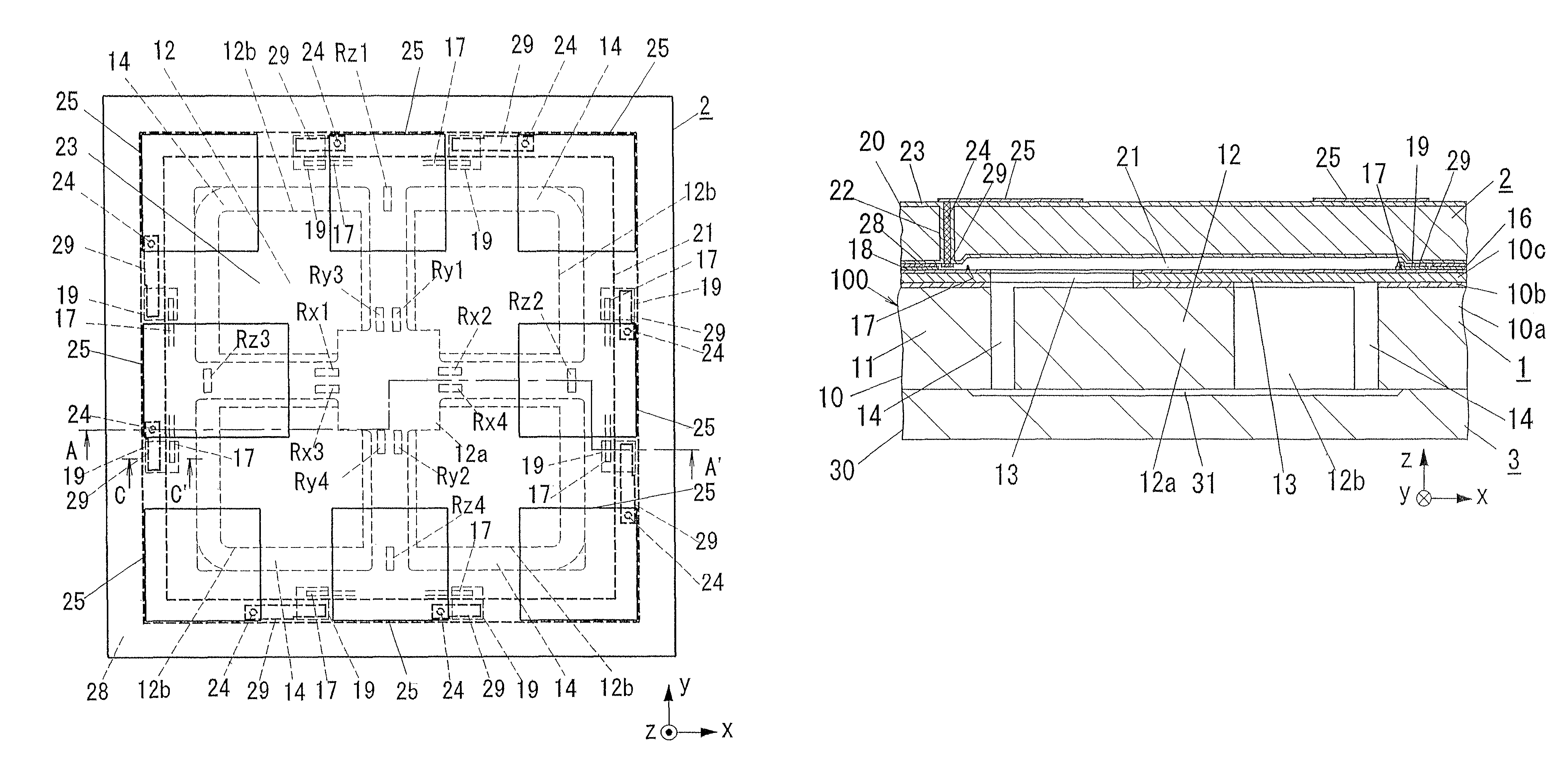
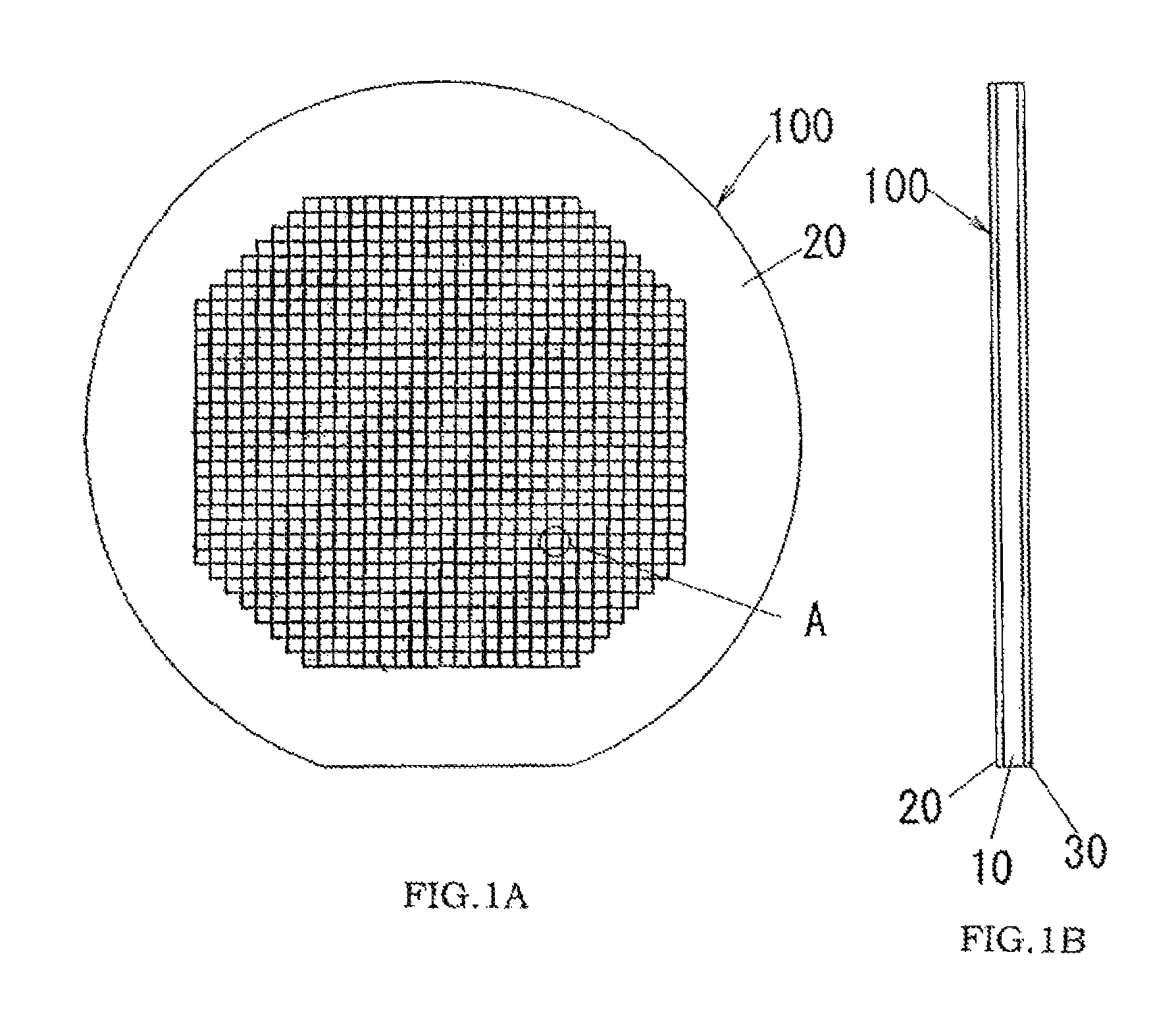
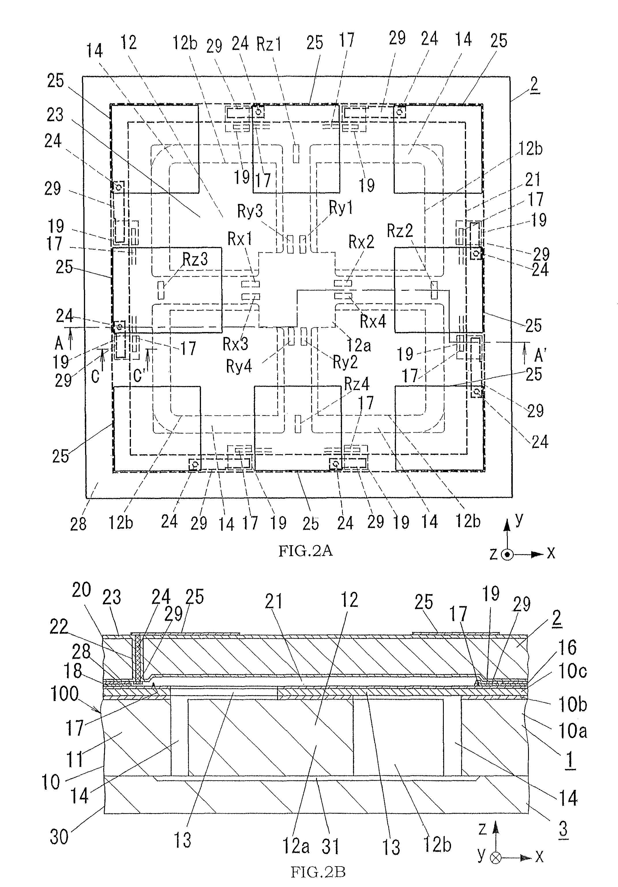
[0043]As shown in FIGS. 1A, 1B, and FIGS. 2A, 2B, a wafer level package structure 100 of the present embodiment has a structure comprised of a semiconductor wafer 10 with a plurality of acceleration sensor units, a first package wafer 20 bonded to one of opposite surfaces of the semiconductor wafer 10, and a second package wafer 30 bonded to the other surface of the semiconductor wafer 10. In the following explanation, a region for forming each of the acceleration sensor units of the semiconductor wafer 10 is defined as a sensor substrate 1. A region facing each of the sensor substrates 1 of the first package wafer 20 is defined as a first package substrate 2. A region facing each of the sensor substrates 1 of the second package wafer 30 is defined as a second package substrate 3.

[0044]In the present embodiment, an SOI wafer used as the semiconductor wafer 10 is composed of a support substrate 10a made of a silicon substrate, an insulating layer (embedded oxide film) 10b such as a s...

second embodiment

[0081]As shown in FIGS. 14A to 14C, a wafer level package structure of the present embodiment is substantially the same as that of the first embodiment except that the sensor substrate 1 has an IC region E2 other than an acceleration sensor unit, and the IC region E2 comprises an integrated circuit (i.e., CMOS IC) using CMOS and operable in collaboration with the piezoresistive elements (Rx1 to Rx4, Ry1 to Ry4, Rz1 to Rz4) of gauge resistances (i.e., a sensing portion). The integrated circuit is formed by integrating a signal processing circuit configured to execute signal processing such as amplification, offset adjustment and temperature compensation to output signals of the bridge circuits (Bx, By, Bz) explained in the first embodiment, and an EEPROM for storing data used in the signal processing circuit. Therefore, in the following explanation, the same components as those in the first embodiment are denoted by the same reference numerals, and the duplicate explanation will be o...

third embodiment

[0094]In each of the above embodiments, the piezoresistance type acceleration sensor was used as the sensor unit. The technical concept of the present invention is also available to the other sensor unit such as a capacitance type acceleration sensor or a gyro sensor. The present embodiment is characterized by forming a gyro sensor unit on a sensor substrate. The other configurations of the present embodiment are substantially the same as those of the first embodiment. Therefore, a bonding portion between the sensor substrate 101 and each of the first and second package substrates (102, 103) can be formed according to the same manner as the first embodiment.

[0095]A wafer level package structure of the present embodiment has a structure comprising a semiconductor wafer with a plurality of gyro sensor units, a first package wafer bonded to one of opposite surfaces of the semiconductor wafer, and a second package wafer bonded to the other surface of the semiconductor wafer. In the foll...


PUM


Abstract

A wafer level package structure with a plurality of compact sensors such as acceleration sensors and gyro sensors is provided. This package structure is composed of a semiconductor wafer with plural sensor units, and a pair of package wafers bonded to both surfaces of the semiconductor wafer. Each of the sensor units has a frame having an opening, a movable portion held in the opening to be movable relative to the frame, and a detecting portion for outputting an electric signal according to a positional displacement of the movable portion. Since the semiconductor wafer is bonded to each of the package wafers by a solid-phase direct bonding without diffusion between a surface-activated region formed on the frame and a surface-activated region formed on the package wafer, it is possible to prevent that variations in sensor characteristics occur due to residual stress at the bonding interface.

Description

TECHNICAL FIELD[0001]The present invention relates to a wafer level packaging technique for manufacturing compact sensor devices such as an acceleration sensor and a gyro sensor.BACKGROUND ART[0002]In recent years, wafer level packaging technique has attracted lots of attention as an appropriate manufacturing technique for sensor devices with chip size package (CSP).[0003]For example, Japanese Patent Early Publication No. 2005-251898 discloses a manufacturing technique for a wafer level package structure 200, as shown in FIGS. 24A and 24B. That is, a sensor wafer 210 and a package wafer 220 are arranged in a face-to-face relation to each other, as shown in FIG. 24A. The sensor wafer 210 has a MEMS (Micro Electro Mechanical System) element 211 and a metal wiring (outgoing electrode) 217 electrically connected to a sensing portion (not shown) of the MEMS element 211. The package wafer 220 has a through-hole wiring 224 electrically connected with the metal wiring 217 and a concave port...

Claims


Application Information

Patent Timeline
Patent Type & Authority Patents(United States)
IPC IPC(8): H01L21/66G01C19/56G01P15/18
CPCB81C1/00269G01C19/56G01P1/023G01P15/0802G01P15/123G01P15/18B81B2201/0235B81B2201/0242B81C2203/0109B81C2203/019B81C2203/038G01P2015/0842
Inventor OKUDO, TAKAFUMISUZUKI, YUJITAKEGAWA, YOSHIYUKIBABA, TORUGOTOU, KOUJIMIYAJIMA, HISAKAZUKATAOKA, KAZUSHISAIJO, TAKASHI
Owner MATSUSHITA ELECTRIC WORKS LTD
Why Eureka
Try Eureka