Alloy, in particular for a bearing coating

a technology of alloy and bearing, applied in the direction of superimposed coating process, mechanical equipment, transportation and packaging, etc., can solve the problems of increasing the requirements of anti-friction elements, the cost of reducing the ability of coatings to adapt, etc., and achieves good run-in properties and high resistance to wear

Inactive Publication Date: 2012-04-03
MIBA SINTER AUSTRIA
View PDF71 Cites 9 Cited by
  • Summary
  • Abstract
  • Description
  • Claims
  • Application Information

AI Technical Summary

Benefits of technology

[0010]The objective of the invention is to propose an alloy and an anti-friction coating for an anti-friction element, which, in addition to exhibiting good run-in properties, also has a high resistance to wear.
[0012]In one embodiment, the mean particle size of the dispersed soft phase and / or hard phase is 1 μm to 100 μm, preferably 5 μm to 20 μm, which ensures an optimal mean particle size of the dispersed phases for the respective application and hence both a sufficient minimum size to guarantee effectiveness and a maximum size which does not impair mechanical strength.

Problems solved by technology

Technical progress made in the engine construction industry has meant that increasingly tough requirements are being placed on many aspects of anti-friction elements, such as plain bearings or thrust washers or sliding bushes for example.
If the emphasis is on good running-in or resistance to galling, the anti-friction coating itself is usually only able to withstand low mechanical stress because the forces to which the shaft or the bearing is exposed are transmitted as a whole and exclusively by the soft anti-friction coating which is therefore susceptible to wear at an early stage.
If, on the other hand, elements are provided which are capable of withstanding such abrasion, they are so at the expense of reduced ability of the coating to adapt.

Method used


Image

  • Alloy, in particular for a bearing coating
  • Alloy, in particular for a bearing coating
  • Alloy, in particular for a bearing coating

Examples


Embodiment Construction

[0036]Firstly, it should be pointed out that the same parts described in the different embodiments are denoted by the same reference numbers and the same component names and the disclosures made throughout the description can be transposed in terms of meaning to same parts bearing the same reference numbers or same component names. Furthermore, the positions chosen for the purposes of the description, such as top, bottom, side, etc., relate to the drawing specifically being described and can be transposed in terms of meaning to a new position when another position is being described. Individual features or combinations of features from the different embodiments illustrated and described may be construed as independent inventive solutions or solutions proposed by the invention in their own right.

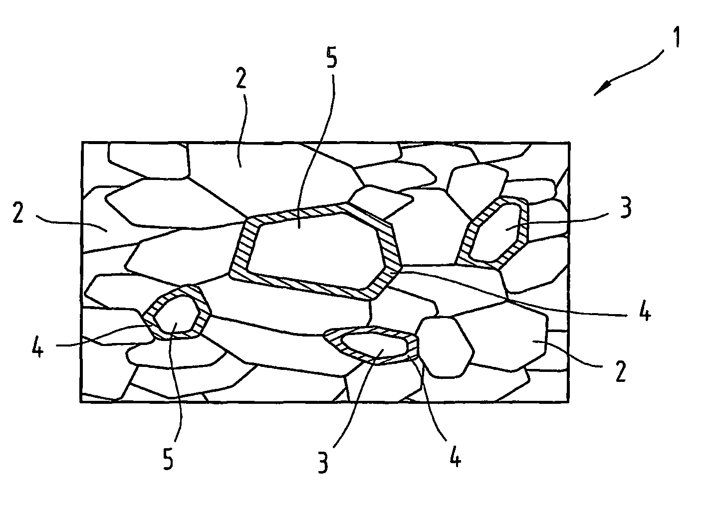
[0037]FIG. 1 provides a schematic diagram illustrating the structure 1 of an anti-friction coating made from the alloy proposed by the invention.

[0038]Particles or grains of a matrix alloy el...


PUM

PropertyMeasurementUnit
mean particle sizeaaaaaaaaaa
thicknessaaaaaaaaaa

Abstract

An alloy, in particular for an anti-friction coating, includes elements which form a matrix and at least a soft phase and / or a hard phase, which soft phase elements and / or hard phase elements form a solid solution or a bond with the matrix element. The soft phase and / or hard phase is dispersed in the matrix and the solid solution or bond is formed only in the region of the phase boundary of the matrix with the soft phase and / or with the hard phase.

Description

CROSS REFERENCE TO RELATED APPLICATIONS[0001]This application is a continuation and claims priority under 35 U.S.C. §120 of U.S. patent application Ser. No. 10 / 575,088 filed May 24, 2006, now U.S. Pat. No. 7,879,453, which application is a national stage application under 35 U.S.C. §371 of PCT Application No. PCT / AT04 / 00338 filed on Oct. 5, 2004, which claims priority under 35 U.S.C. §119 of Austrian Application No. A 1589 / 2003 filed on Oct. 8, 2003, the disclosures of each of which are incorporated by reference. The international application under PCT article 21(2) was not published in English.BACKGROUND OF THE INVENTION[0002]1. Field of the Invention[0003]The invention relates to an alloy, in particular for an anti-friction coating, comprising elements which form a matrix and at least a soft phase and / or a hard phase, which soft phase elements and / or hard phase elements produce a solid solution or bond with the matrix element, an anti-friction coating, in particular a bearing anti...

Claims


Application Information

Patent Timeline
Patent Type & Authority Patents(United States)
IPC IPC(8): B32B5/02B32B15/01B32B15/04B32B15/18B32B15/20F16C32/00C22C1/04C22C1/05C23C4/02C23C24/04C23C28/00F16C33/12
CPCC23C24/04C23C28/028F16C33/14C23C28/027Y10T428/12903F16C2204/12Y10T428/12576Y10T428/12806Y10T428/12736Y10T428/12667Y10T428/12771Y10T428/12028Y10T428/12611Y10T428/12493Y10T428/12708F16C2223/42F16C2223/70F16C2206/80
Inventor LANG, HUBERTRUMPF, THOMAS
Owner MIBA SINTER AUSTRIA
Why Eureka
Try Eureka