Hollow waveguide cavity ringdown spectroscopy

a ring-down spectroscopy and hollow waveguide technology, applied in the field of gas concentration measurement, can solve the problems of reducing the complexity of the apparatus considerably, limiting the sensitivity of the p-crds measurement, and the p-crds is very sensitive to coupling efficiency, so as to increase the cavity energy, reduce the requirement for cavity-to-laser tuning, and greatly increase the spectral spacing between cavity modes

Inactive Publication Date: 2012-04-10
COLORADO SCHOOL OF MINES
View PDF14 Cites 13 Cited by
  • Summary
  • Abstract
  • Description
  • Claims
  • Application Information

AI Technical Summary

Benefits of technology

[0010]A hollow waveguide (HWG) is an optical structure with a hollow core(s) or hollow cross-sectional structure that can be filled with a gas, liquid, or material of differing dielectric properties than the waveguide itself. The waveguide serves to establish a discrete set of transverse electric field profiles (a.k.a. modal fields) and guides these modal fields along the axis of the waveguide (note waveguide does not necessarily need to be straight). Each modal field has its own axial modal velocity which is correlated with the angle of bounce of a geometric ray inside the waveguide. By careful design of the waveguide, light can be made to propagate axially along the waveguide with low attenuation losses of the modal fields. Two fundamental energy dissipative losses of the modal fields exist in the HWG: 1) Radial transmission through the “leaky” waveguide into the surrounding environment; and 2) Absorption losses in the waveguide itself and hollow core (when filled with an absorbing medium). By careful selection of the real and complex refractive indices of the waveguide materials and geometry, the inherent dissipative losses in the HWG can be made sufficiently small to allow cavity ringdown laser absorption spectroscopy to be conducted. The electric modal fields described herein are most commonly associated with optical wavelengths of light although waveguides can be scaled up to operate at longer wavelengths. Exemplary HWG's that have lower cavity attenuation losses (per round trip) than typical CRDS mirrors have been shown to be both theoretically and experimentally feasible. Therefore, HWG-CRDS is technically feasible.
[0013]Pulsed CRDS (P-CRDS) is another version of CRDS that does not necessarily require precision tuning of the cavity. By removing the requirement for a precision tuned laser cavity at certain wavelength spatial resolutions, the overall CRDS process is simplified and the cost of producing the apparatus that supports accurate measurements of gas concentrations is reduced. In the P-CRDS configuration, the length of the laser pulse of light is commonly restricted to ˜one roundtrip time of the cavity (for a 1 m cavity length this is ˜6.7 nanoseconds). As a result, P-CRDS is very sensitive to coupling efficiency since cavity energy is not allowed to accumulate, but rather is limited to the energy contained in a very short pulse. P-CRDS cavity energy is fundamentally limited to the cavity mirror transmissivity. In another embodiment of the invention, the laser light is made to enter the cavity by focusing onto a small spot on the surface of one mirror. The high reflectivity coating is removed or otherwise absent at the laser focal spot, allowing the majority of the light to enter the cavity (transmission is increased up to 1.0 or up to 10,000 times greater than conventional CRDS). The waveguide contains this focused light energy whereas in conventional open cell CRDS, the light energy would be rapidly transmitted out of the cavity after a small number of mirror reflections. In this particular case, in order to minimize attenuation in the HWG, the propagation angle of excited modes may be kept shallow (<5 degrees). A trade-off in extremely shallow injection angles is the loss in reflectivity in the entrance mirror as the F / # of the focusing optic increases (and aperture size due to focus spot size subsequently increases). The HWG is designed such that axial losses are small at the injected light propagation angles where the CRDS measurement will be acquired.
[0014]In P-CRDS, the hollow waveguide allows propagation of a very large continuum of cavity modes including modes with high propagation angles, while conventional CW-CRDS allows transmission only at discrete optical frequencies limited to very low propagation angles. To overcome the discrete frequency problem of conventional cavity-enhanced spectroscopy, the cavity length is varied causing the transmissive frequencies to shift. In accordance with at least some embodiments of the present invention, this will be unnecessary as the nature of the hollow waveguide and method of light injection is to allow a near continuum of light to propagate in the cavity at very low loss. In one embodiment of the invention, a large distribution of excited modal fields of different wavelengths can be simultaneously excited in the HWG and monitored with a high speed spectrometer in order to determine a near instantaneous measurement of spectrally dependent absorption without requiring laser tuning. In such a design, the requirements on laser excitation source linewidth and tuning range are greatly reduced.
[0016]In open cell CRDS, the mode propagation angle is very small (near 0 degrees), the actual small angle dependent on the radius of curvature of the end mirrors. Therefore, as previously discussed, to tune a longitudinal mode of light into the cavity, the wavelength of light in the cavity effectively needs to be resonant with the cavity length. In the HWG-CRDS technique, given the large propagation angles that are possible in the HWG, a longitudinal mode (combination of wavelength of light and propagation angle) must be resonant with the cavity. As such, instead of requiring the cavity length to be actively tuned, in HWG CW-CRDS, the cavity length can be passively fixed and instead the injection angle into the HWG can be precision tuned or alternatively a distribution of propagation angles can be excited by a coupling optic. For a given propagation constant that is resonant with the fixed length cavity, there will be corresponding propagation angle(s) that is(are) resonant with the cavity for a specific wavelength of light such that even a fixed length cell becomes wavelength tunable. In this case a large enough distribution of propagation angles needs to be excited to ensure there is a resonant propagation angle for any wavelength. In one embodiment of the invention, a coupling optic that modulates the injection angle (e.g. acousto-optic, thermally controlled grating, piezoelectric optical coupler) can be used to conduct CRDS or ICOS with a continuous wave laser in an HWG instead of requiring mechanical length changes of the overall cavity. In another embodiment of the invention, a coupling optic excites a large enough distribution of mode propagation angles, a very small subset of which are actually resonant with the cavity for any given wavelength. The large continuum excitation of propagation angles coupled with the selectivity of resonant modes with long pulse lengths approaching CW-CRDS in a fixed length cavity ensures that the cavity is wavelength tunable without requiring mechanical length changes of the overall cavity.

Problems solved by technology

This reduces the complexity of the apparatus considerably compared with other optical cavity-based absorption methods when applied in conjunction with either CRDS or ICOS.
Mode-beating behavior associated with a small set of supported modes in an open cell P-CRDS significantly limits the sensitivity of the P-CRDS measurement (particularly for long pulse lengths greater than the round-trip time of the cavity).
As a result, P-CRDS is very sensitive to coupling efficiency since cavity energy is not allowed to accumulate, but rather is limited to the energy contained in a very short pulse.
A trade-off in extremely shallow injection angles is the loss in reflectivity in the entrance mirror as the F / # of the focusing optic increases (and aperture size due to focus spot size subsequently increases).
Larger or more numerous flow paths will increase optical losses.

Method used


Image

  • Hollow waveguide cavity ringdown spectroscopy
  • Hollow waveguide cavity ringdown spectroscopy
  • Hollow waveguide cavity ringdown spectroscopy

Examples


example

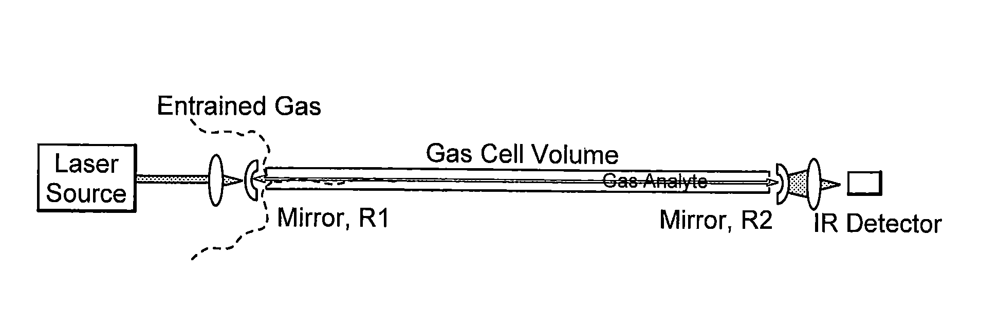
[0059]A HWG for use at 1.66 μm was designed and manufactured. The 1.66 μm HWG allowed measurements of CH4 on the 2ν3 overtone absorption band. An external cavity tunable diode laser, Sacher Lasertechnik Lion Laser (TEMTEC-500-1630-31650) was used with internal piezoelectric modulation of the laser frequency at 1 kHz. The piezoelectric tuning was set to sweep through approximately one free spectral range of an open cell cavity longitudinal mode of the length of the hollow waveguide cavity. A small portion of the laser energy was sampled and directed to a wavemeter (Bristol 621A-NIR), which recorded the average laser frequency at a rate of 4 Hz, using a 20× microscope objective and a single mode fiber. The TEC laser operated in the range of 1573-1675 nm with peak output power >3 mW and bandwidth <5 MHz (20s) and typically <0.5 MHz (50 ms).

[0060]The laser beam was directed by free space optics and focused into the cavity. The cavity was formed by two Newport Ultra-Low Loss SuperMirrors...


PUM

PropertyMeasurementUnit
diameteraaaaaaaaaa
lengthaaaaaaaaaa
propagation angleaaaaaaaaaa

Abstract

Laser light is confined in a hollow waveguide between two highly reflective mirrors. This waveguide cavity is used to conduct Cavity Ringdown Absorption Spectroscopy of loss mechanisms in the cavity including absorption or scattering by gases, liquid, solids, and / or optical elements.

Description

[0001]This application claims priority from U.S. Provisional Patent Application No. 60 / 892,762 filed Mar. 2, 2007, the disclosure of which is hereby incorporated herein by reference.[0002]The U.S. Government has a paid-up license in this invention and the right in limited circumstances to require the patent owner to license others on reasonable terms as provided for by the terms of Grant Number NNG04GN40G awarded by NASA.FIELD OF THE INVENTION[0003]This invention relates generally to gas concentration measurement by laser light absorption, laser absorption cavity ringdown spectroscopy, and more particularly to the design, manufacturing, and use of a hollow waveguide cavity ringdown spectroscopy gas sensing instrument.BACKGROUND[0004]Gas concentration measurement by light absorption makes use of the nature of molecular and atomic gases to absorb portions of the electromagnetic spectrum that correspond to energy transitions of the absorbing gas species. There are several methods for u...

Claims


Application Information

Patent Timeline
Patent Type & Authority Patents(United States)
IPC IPC(8): G01N21/00
CPCG01J3/02G01J3/0218G01J3/42G01N21/39G01N15/06G01N21/3504G01N2015/0693G01N2021/391G01N2021/399
Inventor DREYER, CHRISMUNGAS, GREG S.
Owner COLORADO SCHOOL OF MINES
Why Eureka
Try Eureka