
Process for biomass conversion to synthesis gas

a biomass and synthesis gas technology, applied in the field of renewable fuel systems, can solve the problems of high impurities of natural gas feedstock for steam reforming, complex and expensive equipment, and the expected disruption of the global ecosystem and the lives of millions of individuals across the plan

Active Publication Date: 2012-05-08
COOL PLANET ENERGY SYST
View PDF58 Cites 52 Cited by
  • Summary
  • Abstract
  • Description
  • Claims
  • Application Information

AI Technical Summary

Benefits of technology

[0016]Embodiments of the invention use a novel type of char created from a bi...

Problems solved by technology

The rise of global temperatures is expected to produce significant disruptions to the global ecosystem and to the lives of millions of individuals across the planet.
A problem with these approaches is that the synthesis gas produced from coal and the natural gas feedstock for steam reforming has high impurities (particularly sulfur-containing compounds), or requires complicated and expensive equipment to clean impurities in the produced synthesis gas.
Synthesis gas obtained directly from coal gasification is deficient in hydrogen.
Therefore, the H2 / CO ratio must be adjusted using complicated and expensive equipment.
Although some pyrolyzers are focused simply on producing synthesis gas, there is considerable effort in the development of milder pyrolyzing conditions, which typically results in a condensed liquid commonly known as bio-oil or pyrolysis oil.
The fundamental problem with the resultant pyrolysis oil is that it is made up of hundreds to thousands of compounds, which are the result of subjecting the raw biomass to a wide range of temperature, time, and pressure profiles in bulk.
When this process is complicated by the thousands of major bio-compounds in the original bio-feedstock, the result is a nearly intractable array of resultant compounds all mixed together.
Pyrolysis oils from such processes are typically not thermodynamically stable.
Also, attempts to re-gasify pyrolysis oil typically result in additional chemical reactions, which produce additional biochar and a shift to lower molecular weight components in the resulting gas stream Although fairly high yields of pyrolysis oil can be achieved in laboratory scale experiments, larger industrial scale demonstration projects typically produce much lower yield.
Thus the pyrolysis oil is not stable enough nor the biochar is pure enough for further processing without needing complicated and expensive equipment to remove impurities in the synthesis gas.

Method used


Image

  • Process for biomass conversion to synthesis gas
  • Process for biomass conversion to synthesis gas
  • Process for biomass conversion to synthesis gas

Examples


Embodiment Construction

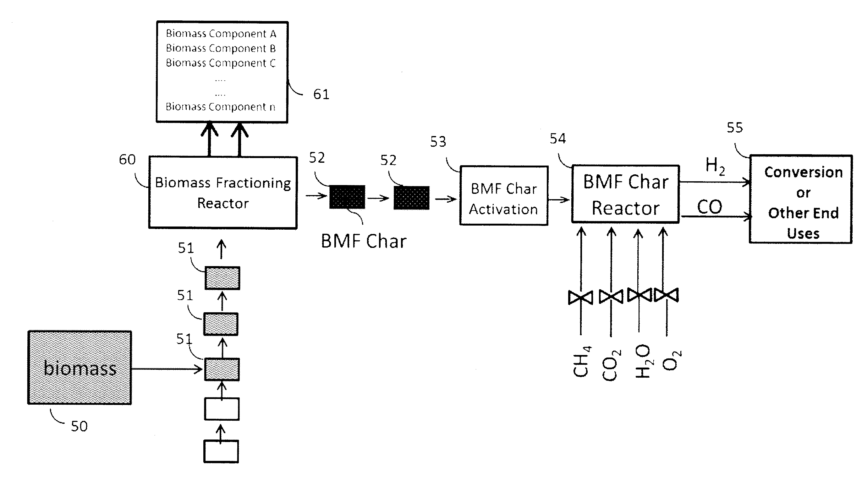
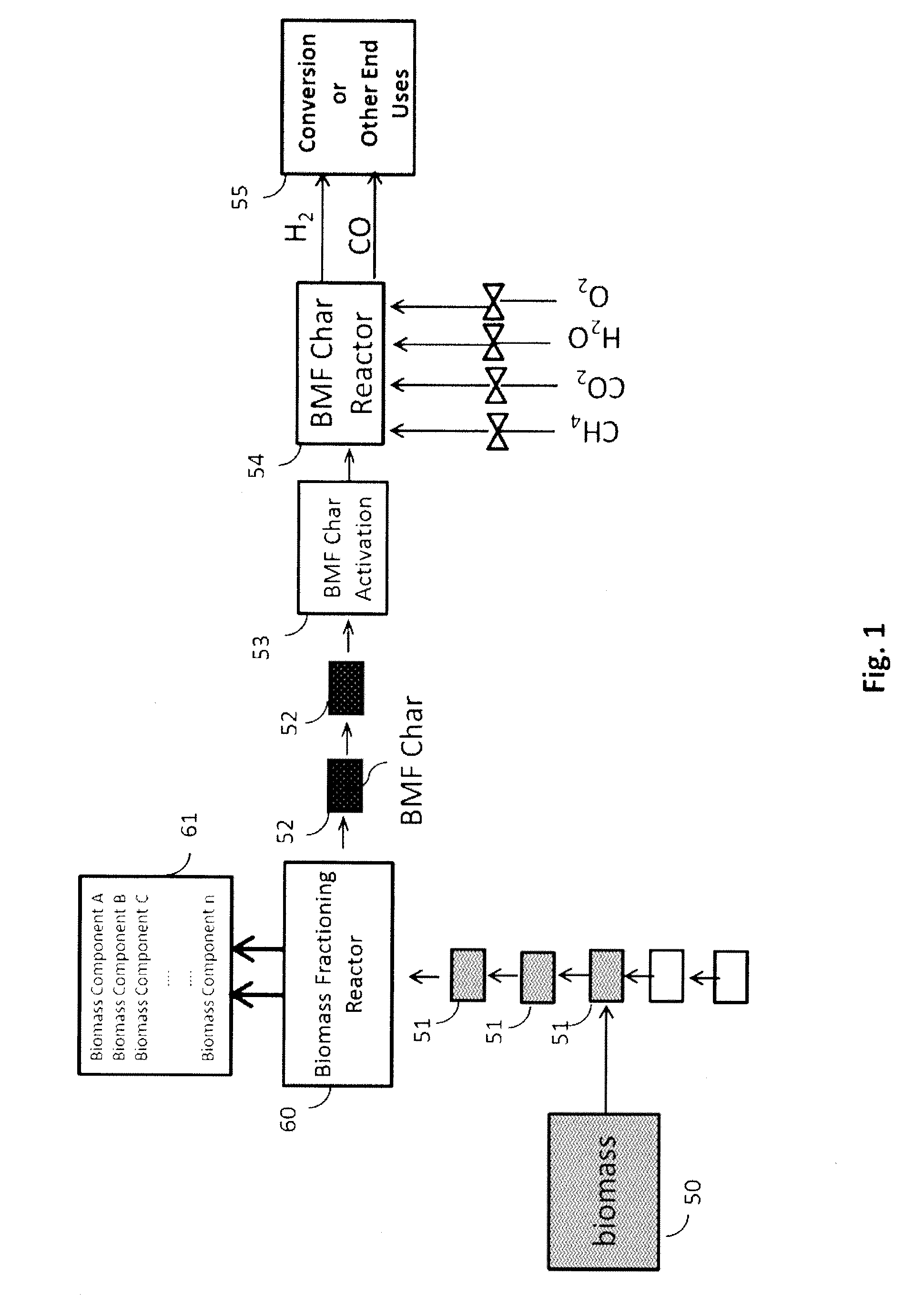
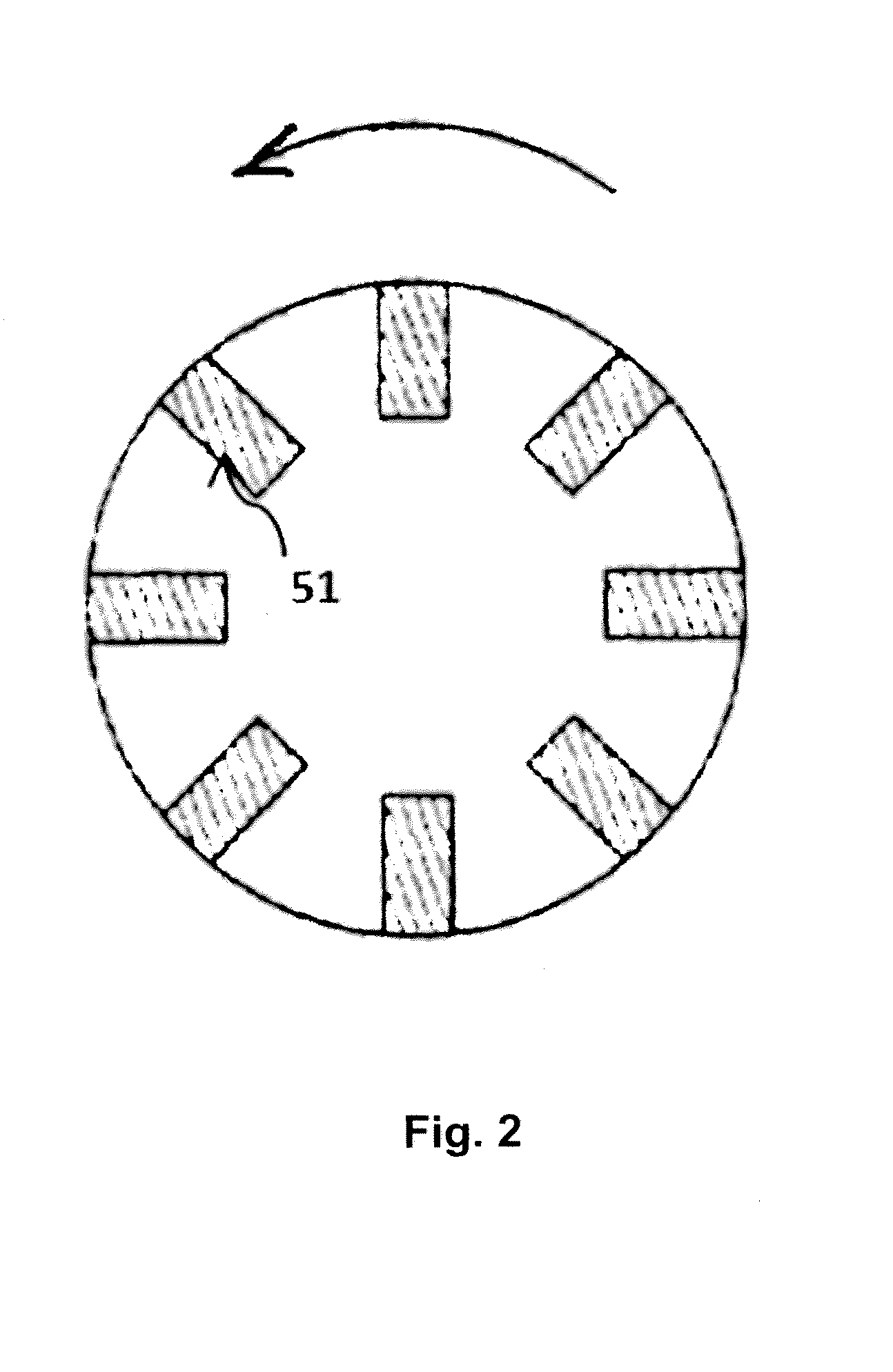
[0012]The above-described methods of generating synthesis gas from bio-char differ substantially from the methods of the invention, which utilize a novel type of char referred as biomass fractionated (BMF) char. The BMF char may be generated according principles disclosed in co-filed U.S. patent application Ser. No. 13 / 103,905 entitled “Method for Biomass Fractioning by Enhancing Thermal Conductivity.” BMF char is generated in a unique manner using a biomass fractioning reactor in which biomass is fractioned into thin sheets, and the thin sheets are subject to specific temperature ramps and pressure shocks.

[0013]According to various embodiments of the invention, the adjustment of synthesis gas ratio is unique in that it is controlled by the nature and quantity of the feedstock. Depending on whether the feedstock is hydrogen-rich or oxygen-rich, a wide spectrum of synthesis gas compositions may be obtained.

[0014]Another embodiment features a method for producing synthesis gas from bi...


PUM


Abstract

Biomass is processed through a biomass fractioning system that creates, through the application of selective temperature ramps and pressure shocks, a series of useful volatile components and BMF char, wherein the BMF char is reacted sacrificially with any one stream of methane, carbon dioxide, steam or oxygen to create highly pure synthesis gas with a controllable range of compositions. The resulting synthesis gas may be used in any desired manner, including conversion to oxygenates such as methanol and dimethyl ether, and to hydrocarbons.

Description

TECHNICAL FIELD[0001]The present invention relates generally to systems for making renewable fuels, and snore particularly to the conversion of char generated using a reactor to produce highly pure synthesis gas that can ultimately generate value added chemicals and renewable fuels.DESCRIPTION OF THE RELATED ART[0002]The planet is warming and solutions are being sought to decrease the magnitude of this effect. Global temperatures are expected to increase by at least 2 degrees Celsius by the middle of the century. The rise of global temperatures is expected to produce significant disruptions to the global ecosystem and to the lives of millions of individuals across the planet. Processes that reduce carbon emissions in a significant manner are urgently needed. The Fischer-Tropsch process converts a mixture of carbon monoxide and hydrogen (synthesis gas) into hydrocarbons of varying numbers of carbon, which can then be upgraded to diesel, gasoline, aviation fuel, lubricants and chemica...

Claims


Application Information

Patent Timeline
IPC IPC(8): C01B3/38C01B3/24C01B32/336
CPCC01B3/34C01B31/10C10G1/02C01B3/36C10J3/62C10B53/02C01B31/081C10K3/00C10G2300/1011C01B2203/0211C01B2203/025C01B2203/061C01B2203/062C10J2300/0916C10J2300/0976Y02E50/14A61P31/00C01B32/324C01B32/336Y02E50/10Y02P20/145Y02P30/20
Inventor CHEIKY, MICHAELMALYALA, RAJASHEKHARAMSILLS, RONALD A.
Owner COOL PLANET ENERGY SYST
Learn More