
Transition temperature microscopy

a transition temperature and microscopy technology, applied in the field of new microscopy, can solve the problems of inability to spatially resolve, difficult to attribute the contrast to a quantifiable physical property, and no current technique provides high-resolution images of transition temperatures. achieve the effect of high-resolution measurements

Active Publication Date: 2012-05-15
BRUKER NANO INC
View PDF18 Cites 24 Cited by
  • Summary
  • Abstract
  • Description
  • Claims
  • Application Information

AI Technical Summary

Benefits of technology

The patent describes a technique called transition temperature microscopy that can measure the temperature at which materials change from one phase to another. This technique can provide valuable information about the structure and composition of materials, including identifying different components in a mixture, identifying different forms of a drug, and identifying different regions of a material. Overall, transition temperature microscopy can provide high-resolution data on materials that can help scientists and engineers better understand and improve the properties of materials.

Problems solved by technology

In many cases, it is difficult to attribute the contrast to a quantifiable physical property.
Conventional micro and nano thermal analysis measurements, however are measured manually at single points or a handful of points without the ability to spatially resolve detailed variations in thermal transition temperatures.
As such, no current technique provides high resolution images of transition temperatures.

Method used


Image

  • Transition temperature microscopy
  • Transition temperature microscopy
  • Transition temperature microscopy

Examples


Embodiment Construction

[0013]This invention provides high resolution microscope images of thermal transition temperatures.

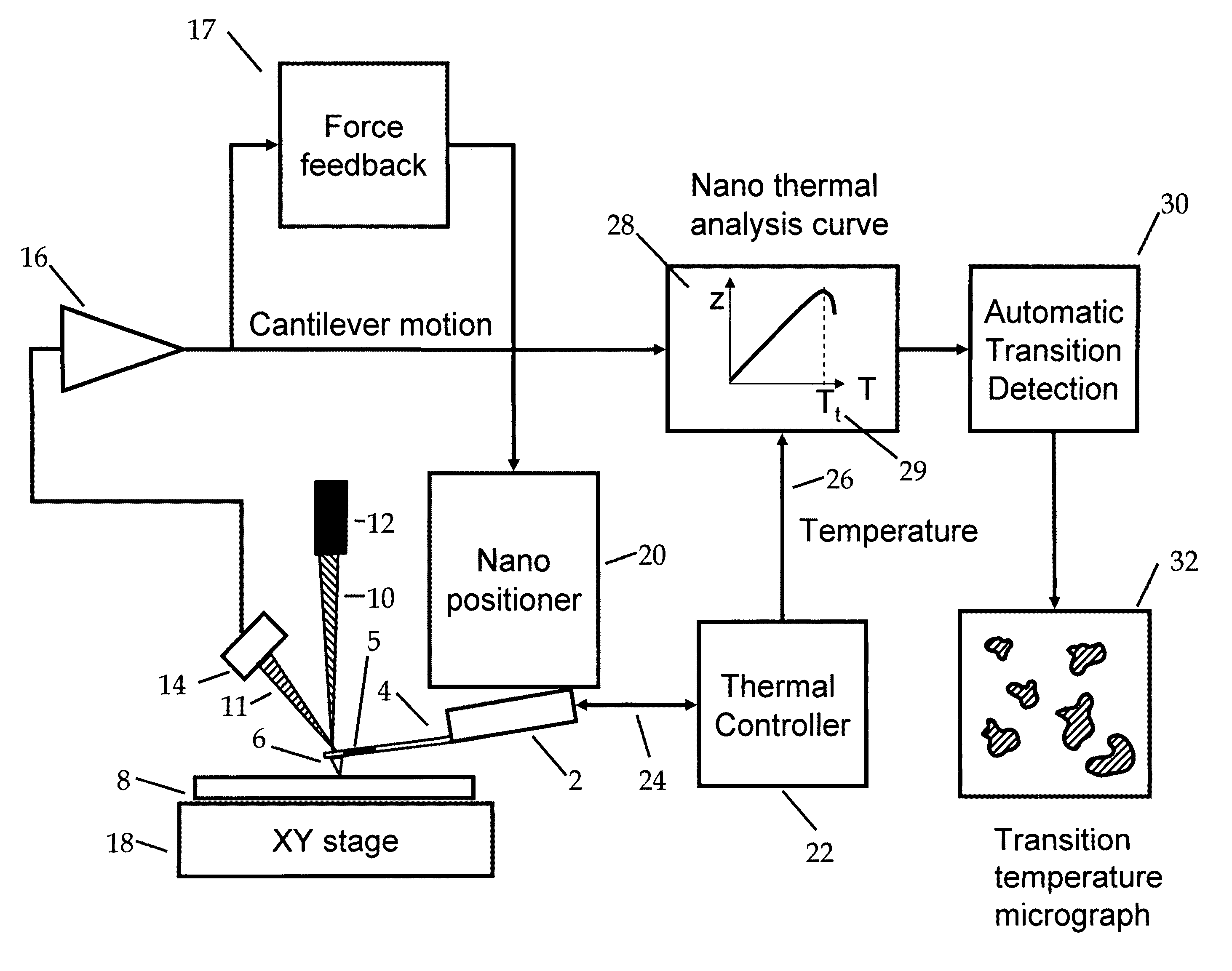
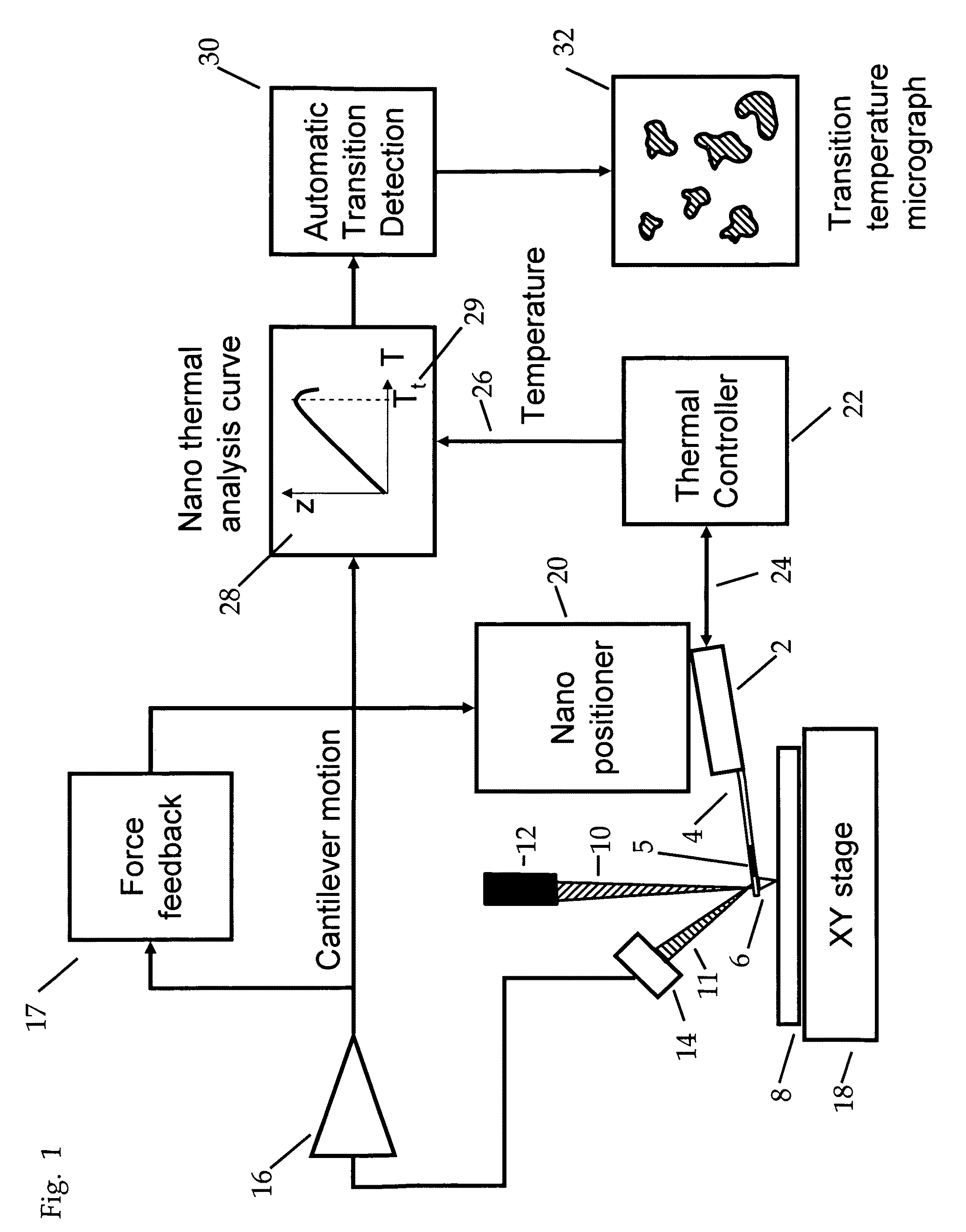
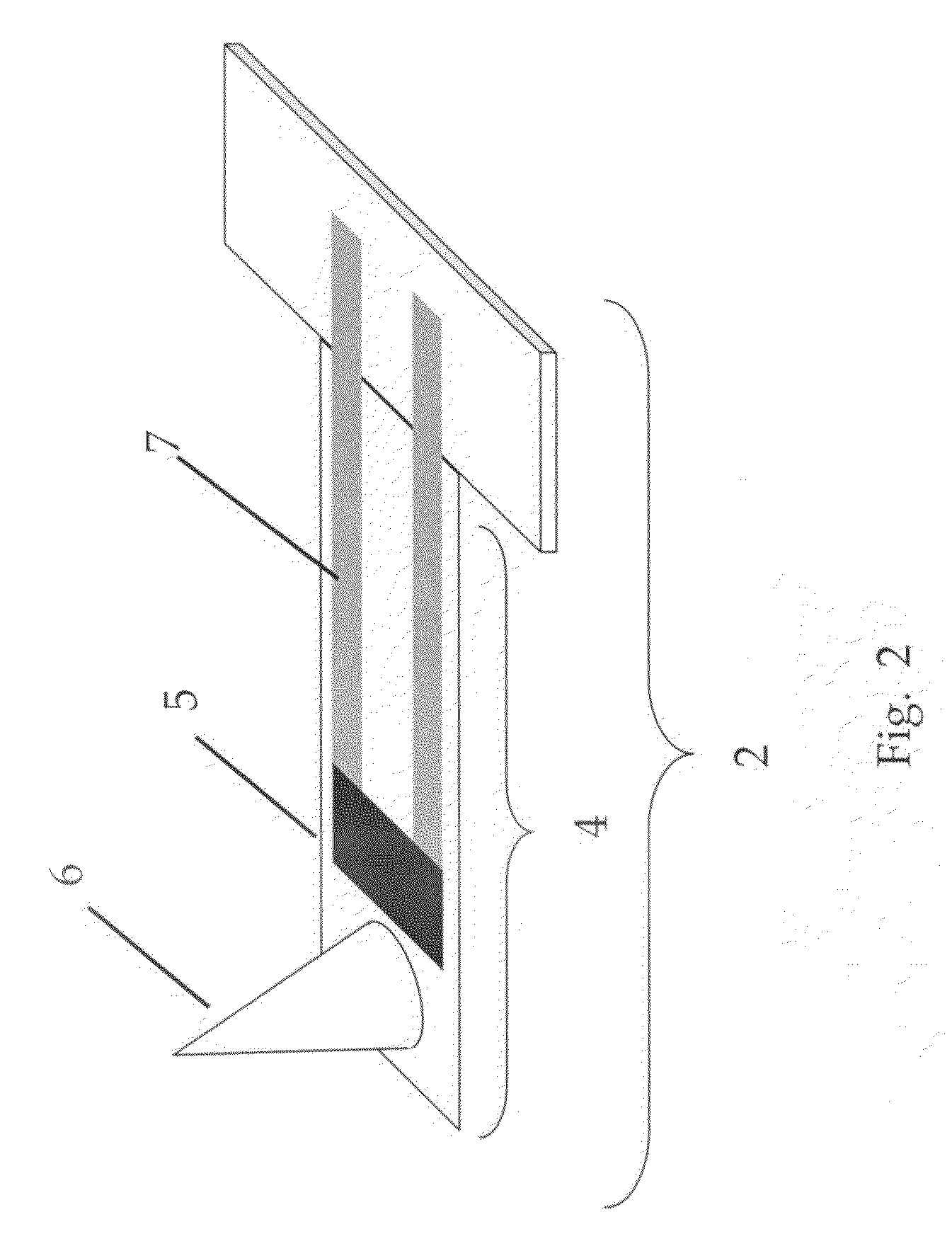
[0014]FIG. 1 is a simplified schematic diagram of an apparatus for transition temperature microscopy. A probe 2 comprising a cantilever 4 and a heatable probe tip 6 is brought close to a surface of sample 8. Thermal controller 22 supplies a control signal to a heater region 5 of the probe. A portion of the heat from the probe flows from the probe tip 6 into the sample 8. The increase in sample temperature causes a detectable probe data signal sensed by the probe. In one embodiment the detected probe data signal is the motion of the cantilever. In this embodiment, the temperature rise of the sample may cause a thermal expansion of the sample. This thermal expansion may be detected by recording a change in the bend, vertical position, and / or oscillation of the cantilever. One simple method is to record the deflection of the cantilever 4 as a function of the applied heater control signal ...


PUM

PropertyMeasurementUnit
elapsed timeaaaaaaaaaa
thicknessesaaaaaaaaaa

Abstract

A system and method for automatic analysis of temperature transition data over an area of a sample surface. The system relies on the use of a microfabricated probe, which can be rapidly heated and cooled and has a sharp tip to provide high spatial resolution. The system also has fast x-y-z positioners, data collection, and algorithms that allow automatic analysis of and visualization of temperature transition data.

Description

BACKGROUND OF THE INVENTION[0001]This invention relates to a novel form of microscopy that allows high resolution mapping of thermal transitions of materials. Measurement of thermal properties of materials is critical to the development of novel materials, including polymers and pharmaceuticals. Understanding the performance of materials at different temperatures is essential for applications like automotive components, construction materials, food packaging, consumer electronics, drug delivery and many others. A key aspect of a material's thermal performance is provided by its thermal transition temperatures, for example rubber / glassy transitions, and melting transitions. Many composite materials are manufactured with micro and nanoscale blends of different materials, for example plastic materials for stiffness and rubbery materials for energy absorption. Conventional techniques for imaging these materials includes TEM and Atomic Force Microscopy (AFM). In AFM, phase imaging, as de...

Claims


Application Information

Patent Timeline
Patent Type & Authority Patents(United States)
IPC IPC(8): G01N25/00G01K3/00G01K7/00
CPCB82Y35/00G01Q60/58G01Q30/04
Inventor KJOLLER, KEVINSAHAGIAN, KHORENGOTTHARD, DOUGKURTZ, ANTHONYPRATER, CRAIGSHETTY, ROSHANREADING, MICHAEL
Owner BRUKER NANO INC
Learn More