Terahertz radiation device using polar semiconductor materials and method of generating terahertz radiation

a technology of terahertz radiation and semiconductor materials, applied in the field of radiation emitting crystals, can solve the problems of limited thz pulse energy, thz radiation, external bias voltage, etc., and achieve the effects of enhancing terahertz radiation, improving thz generation efficiency, and enhancing terahertz radiation generation

Active Publication Date: 2012-06-19
ARMY US SEC THE
View PDF17 Cites 5 Cited by
  • Summary
  • Abstract
  • Description
  • Claims
  • Application Information

AI Technical Summary

Benefits of technology

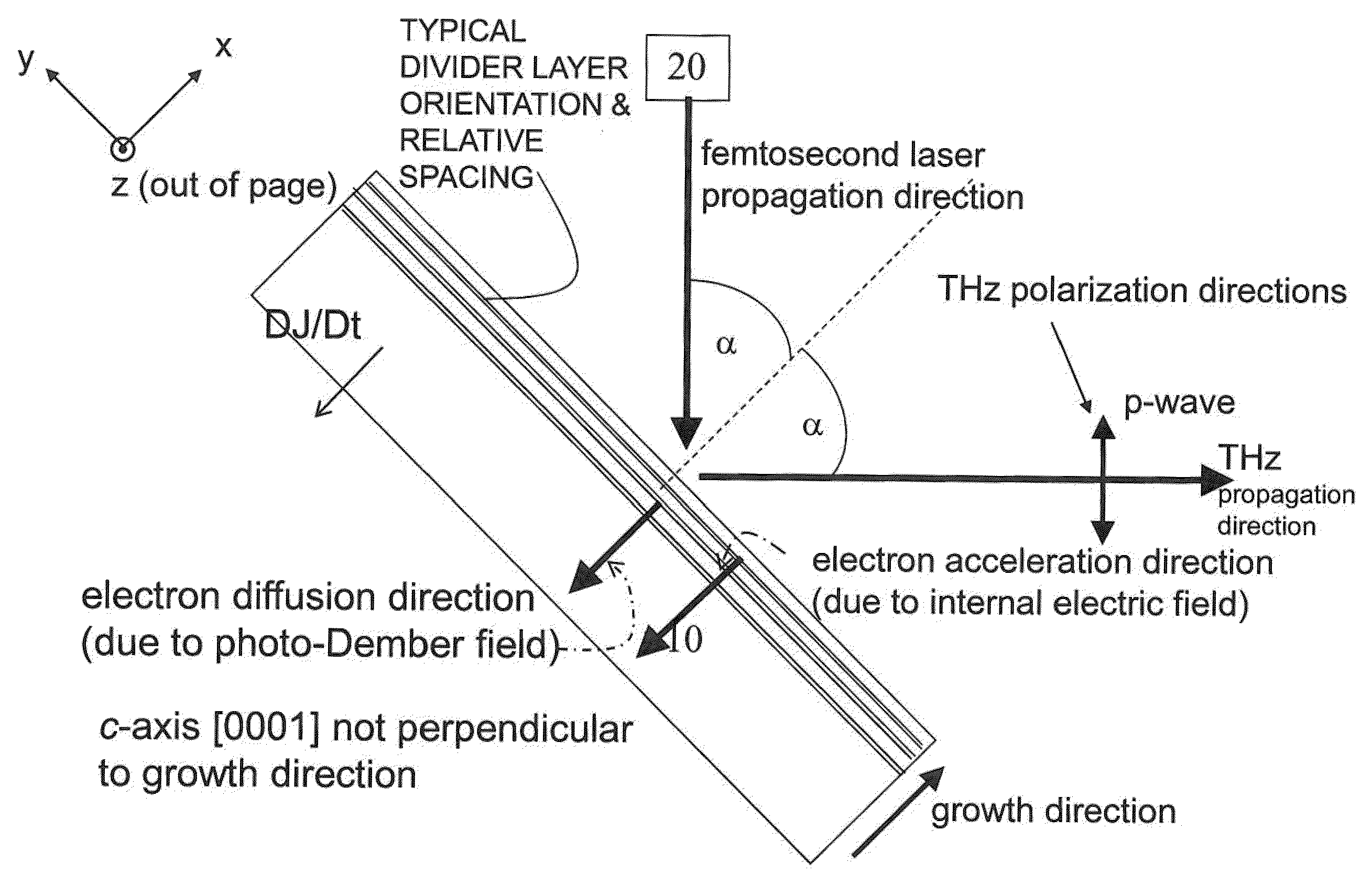
[0013]A preferred embodiment of the present invention improves the efficiency of THz generation through, inter alia, the creation of an internal electric field which aids electron diffusion. The internal electric field may be created through spontaneous and piezoelectric polarization in the vertical (growth) direction. A preferred embodiment comprises transport and divider layers (or regions) in polar compound semiconductors grown along a polar direction; that is, a direction in which the surface is terminated by all cation or anion atoms. The internal electric field is created when the spontaneous and / or piezoelectric polarization is terminated at the interfaces of transport / divider layers (or regions). The interface between the transport and divider layers (or regions) forms boundaries at which the internal electric polarization terminates leading to charges accumulating at the boundaries, and creation of internal electric fields oriented along the polar axis.
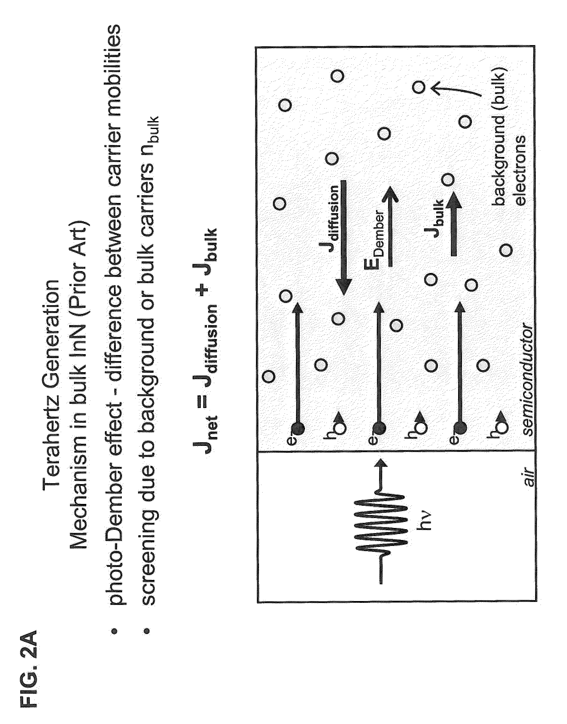
[0014]The transport layers or regions are formed of a material having a bandgap different from the material forming the divider layers. Because of the difference in band gap, result in the termination of the spontaneous and piezoelectric internal electric polarization along the c-axis of the wurtzite material at the interface between the transport and divider layers (or regions). For example, the divider layers or regions may be made of indium gallium nitride and the transport layers may be made of gallium nitride; both of which materials may be grown by vapor deposition or epitaxy (forming heterojunctions) on a polar or semipolar substrate. The plane of the layers may be perpendicular to the polar axis, although being not parallel to the polar axis is sufficient. When the preferred embodiment is irradiated by a pulsed source of duration less than one picosecond, a time-varying and spatially nonuniform distribution of carriers is created in the growth direction of the polar crystal material within the transport and divider layers (or regions), thereby generating a first time-varying current due to diffusion of the carriers. The internal electric fields accelerate the carriers generated by the pulsed radiation source to produce a second time-varying current that is in addition to the first time-varying current, thereby enhancing the generation of terahertz radiation. The first time-varying current due to diffusion and the second time-varying current that is produced by the internal electric field are in the same direction (parallel to the polar axis) and are additive. When the divider layers (or regions) are formed of a material that has a smaller band gap than the bandgap of the material forming the transport layers, the divider layers operate to collect background carriers thereby enhancing the first time-varying current due to diffusion and the second time-varying current produced by the internal electric field such that terahertz radiation is enhanced. Also, as an additional benefit of the divider layers (or regions), the time-varying Dember field produced by the first time-varying current is not screened by the presence of back ground carriers (from doping, etc.).

Problems solved by technology

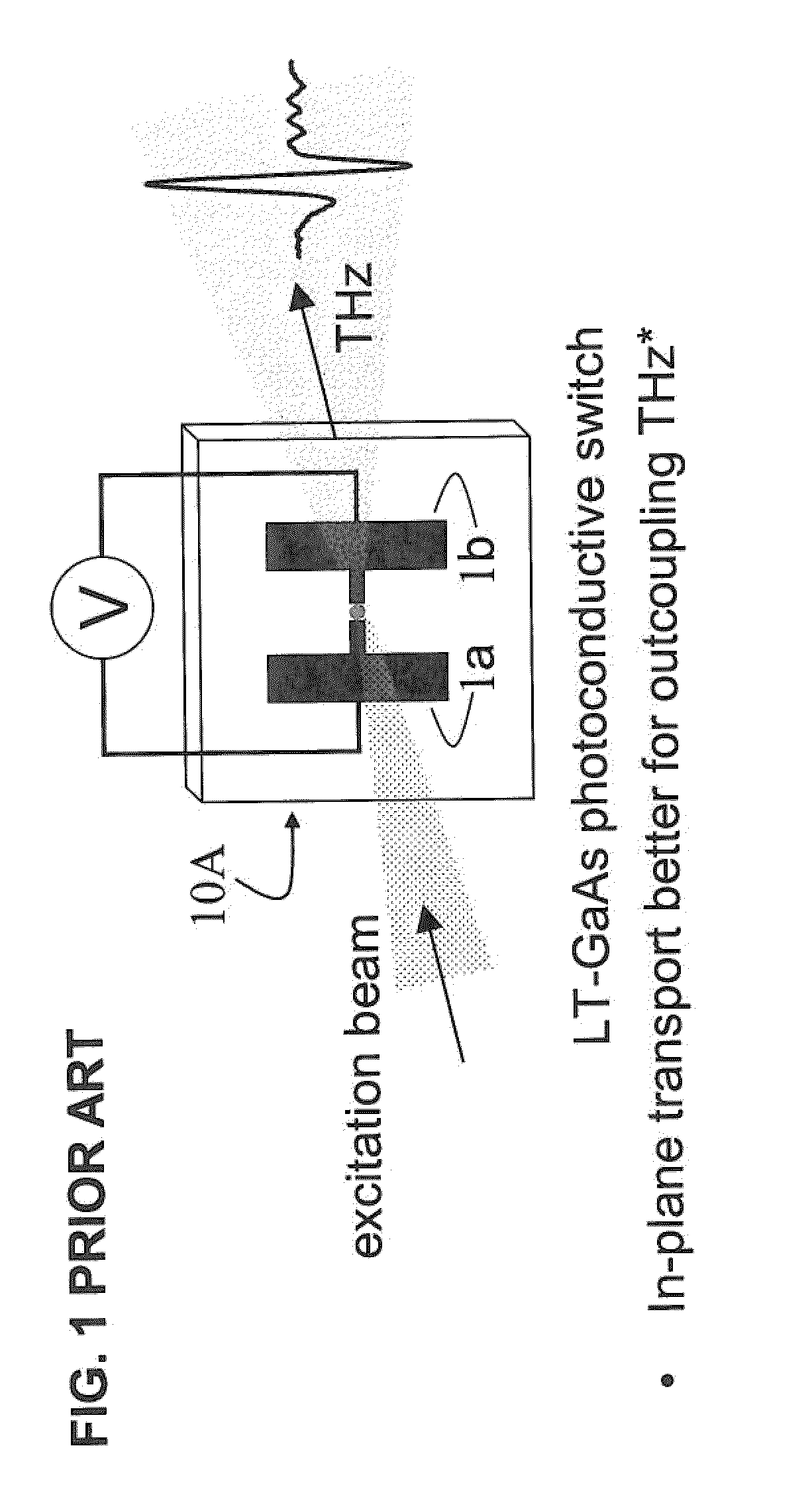
One disadvantage of this approach is that metal electrodes with kV voltages across them must be used to create the THz radiation.
Another disadvantage is that the external bias voltage, and therefore the THz pulse energy, is limited by dielectric breakdown in air to less than 30 kV / cm in theory, but in practice 10 kV / cm is rarely exceeded.
Although the geometry of the biased photoconductive antennas is more favorable for coupling out the THz radiation than that for other semiconductor-based THz sources employing transport normal to the surface, these photoconductive switches require electrode processing and an external bias voltage, which is limited by the dielectric strength of air, to establish an in-plane electric field.

Method used


Image

  • Terahertz radiation device using polar semiconductor materials and method of generating terahertz radiation
  • Terahertz radiation device using polar semiconductor materials and method of generating terahertz radiation
  • Terahertz radiation device using polar semiconductor materials and method of generating terahertz radiation

Examples


Embodiment Construction

[0036]The present invention now will be described more fully hereinafter with reference to the accompanying drawings, in which embodiments of the invention are shown. However, this invention should not be construed as limited to the embodiments set forth herein. Rather, these embodiments are provided so that this disclosure will be thorough and complete, and will fully convey the scope of the invention to those skilled in the art. In the drawings, the thickness of layers and regions may be exaggerated for clarity. Like numbers refer to like elements throughout. As used herein the term “and / or” includes any and all combinations of one or more of the associated listed items.

[0037]The terminology used herein is for the purpose of describing particular embodiments only and is not intended to limit the full scope of the invention. As used herein, the singular forms “a”, “an” and “the” are intended to include the plural forms as well, unless the context clearly indicates otherwise. It wil...


PUM


Abstract

A method and device for generating terahertz radiation comprising a plurality of layers of polar crystal material operative to emit terahertz radiation; the plurality of layers comprising transport layers and divider layers, the plane of the layers being not parallel to the polar axis, the interface between the transport layers and divider layers forming boundaries at which the internal electric polarization terminates leading to charges accumulating at the boundaries, and creation of internal electric fields oriented along the polar axis.

Description

GOVERNMENT INTEREST[0001]The invention described herein may be manufactured, used, and / or licensed by or for the United States Government.CROSS-REFERENCE TO RELATED APPLICATIONS[0002]This application claims the priority of U.S. application Ser. No. 13 / 042,775 entitled “Terahertz Radiation Device and Method of Generating Terahertz Radiation,” filed Mar. 8, 2011, by Dr. Michael Wraback, et al., and also claims priority of U.S. application Ser. No. 12 / 435,797 entitled “Method and Apparatus for Enhanced Terahertz Radiation from High Stacking Fault Density,” filed May 5, 2009, by Dr. Grace Metcalfe, et al. (U.S. Pat. No. 7,919,764; issue date Apr. 5, 2011) and U.S. Provisional Application No. 61 / 050,890 filed May 6, 2008. U.S. application Ser. Nos. 13 / 042,775, 12 / 435,797 and 61 / 050,890 are hereby incorporated herein by reference.FIELD OF THE INVENTION[0003]This invention relates generally to radiation emitting crystals, and more particularly to crystal structures which provide a source o...

Claims


Application Information

Patent Timeline
Patent Type & Authority Patents(United States)
IPC IPC(8): H01L33/04H01L33/32H01L33/28
CPCG02F1/353G02F1/3551G02F2203/13
Inventor WRABACK, MICHAELSHEN, PAUL H
Owner ARMY US SEC THE
Why Eureka
Try Eureka