Braze foil for high-temperature brazing and methods for repairing or producing components using a braze foil

a high-temperature brazing and high-temperature brazing technology, applied in the field of materials science, can solve the problems of undesirable cracks in materials, high mechanical load on turbine rotor blades in particular, and increase the efficiency of the plant, and achieve relatively large gaps, easy brazing, and relatively wide brazing gaps

Inactive Publication Date: 2012-08-07
ANSALDO ENERGIA IP UK LTD
View PDF57 Cites 24 Cited by
  • Summary
  • Abstract
  • Description
  • Claims
  • Application Information

AI Technical Summary

Benefits of technology

[0032]If large filler particles and / or higher proportions of the filler particles are used in the braze coating, larger spacings between the component elements can also be easily brazed, although this takes place without the formation of an epitaxial microstructure.
[0033]It is furthermore advantageous if the braze foil and / or the nano braze powder comprises at least one melting point depressant, in a content which is at least as high as in common, commercially available braze alloy compositions.
[0034]An increased content of melting point depressants (up to twice as high as in common, commercially available braze alloy compositions, for example about 3 to 7% by weight B, up to 15% by weight Si, and up to 15% by weight P) is particularly advantageous here, because then the known effect of the relatively small particle size of the powder particles on the reduction in the melting temperature and the action of the melting point depressants are strengthened.
[0035]In one embodiment variant, the braze foil can additionally comprise, on its surface, filler particles having a particle size in the range of 1-30 μm and a proportion in the overall powder mixture of 1 to 40% by weight. It is preferable for the particle size of the filler particles to be in the range of 1 to 15 μm and for the proportion of the filler particles in the overall mixture to be 5 to 20% by weight. It is then particularly advantageously possible to braze relatively wide gaps, and thus to bridge relatively large spacings between the parts to be connected. In addition, it is possible, depending on the type and proportion of the filler material used, to influence the properties of the brazed region. However, the solidified braze material then does not necessarily have the same single crystal or directionally solidified microstructure as the surrounding base material.
[0036]In one embodiment, it is also possible for the surface of the filler particles to be thinly coated with particles of the braze powder. The coating of the upper and lower side of the braze foil and the coating of the filler particles with the particles of the braze powder are particularly advantageous if the coating comprises only one layer up to a maximum of 10 layers of the particles of the braze powder.

Problems solved by technology

On account of this combination of properties, the intake temperature of the turbine can be increased greatly when using such, nevertheless very expensive, materials, e.g., in gas turbines, and therefore the efficiency of the plant increases.
In addition to these high thermal stresses, turbine rotor blades in particular are also subjected to high mechanical loading, for example.
During operation of the turbine, this as a whole can lead to the creation of undesirable cracks in the material, and therefore components damaged in this way either have to be replaced by new parts or else repaired.
Since, as already mentioned above, the production of single crystal or directionally solidified new turbine components is extremely expensive, however, and is complicated in the case of large parts in terms of a sufficient material quality (continuous single crystal or directionally solidified structure), an attempt is usually made to repair the damaged component present, i.e., the functionality of the component should be restored by the repair and the repaired component should then be used again for a further maintenance period in the turbine.
Compared to the repair of damaged components having a conventional polycrystalline microstructure, however, the repair of damaged single crystal or directionally solidified gas turbine components is significantly more difficult, since the repaired regions of the single crystal or directionally solidified components should also have a corresponding single crystal or directionally solidified microstructure; otherwise, the properties are undesirably impaired in the repaired region.
The braze alloy solidifies as a consequence of the reduction in the boron concentration, whereas the base material has an increased boron concentration in the region surrounding the braze alloy, which can disadvantageously lead to the precipitation of brittle borides.
Furthermore, it is also disadvantageous that the braze material, in contrast to the base material, in many cases cannot have a single crystal or directionally solidified structure after the brazing on account of the major action of heat.
The braze material also solidifies in an unordered polycrystalline structure and therefore disadvantageously has poorer properties than the single crystal or directionally solidified base material.
It is known from EP 1 759 806 A1 and from U.S. Patent App. Pub. No. 2004 / 0050913 A1 to reduce the melting point of a braze alloy by reducing the particle size (to values in the nanometer range) of the braze alloy, which is suspended in a carrier liquid, but this is done with the aim of reducing the proportion of melting point depressants, e.g., B and Si, in the braze alloy or of removing these depressants entirely from the braze alloy, since they are disadvantageously responsible for the formation of brittle phases, which, inter alia, cause an undesirable loss of ductility of the material.
This technical solution has the disadvantage that, on account of the sole use of nanoparticles as the solid braze alloy component of the suspension, strong shrinkage occurs after the brazing and therefore the quality of the brazed joint needs to be improved.
This technical solution has the disadvantage that, on account of the sole use of nanoparticles in the crack, strong shrinkage occurs after the brazing and therefore the quality of the brazed joint would appear to need improvement.
There is only a small risk of recrystallization.
However, the solidified braze material then does not necessarily have the same single crystal or directionally solidified microstructure as the surrounding base material.

Method used


Image

  • Braze foil for high-temperature brazing and methods for repairing or producing components using a braze foil
  • Braze foil for high-temperature brazing and methods for repairing or producing components using a braze foil
  • Braze foil for high-temperature brazing and methods for repairing or producing components using a braze foil

Examples


Embodiment Construction

[0044]In the text which follows, the invention is explained in more detail on the basis of exemplary embodiments and the drawings.

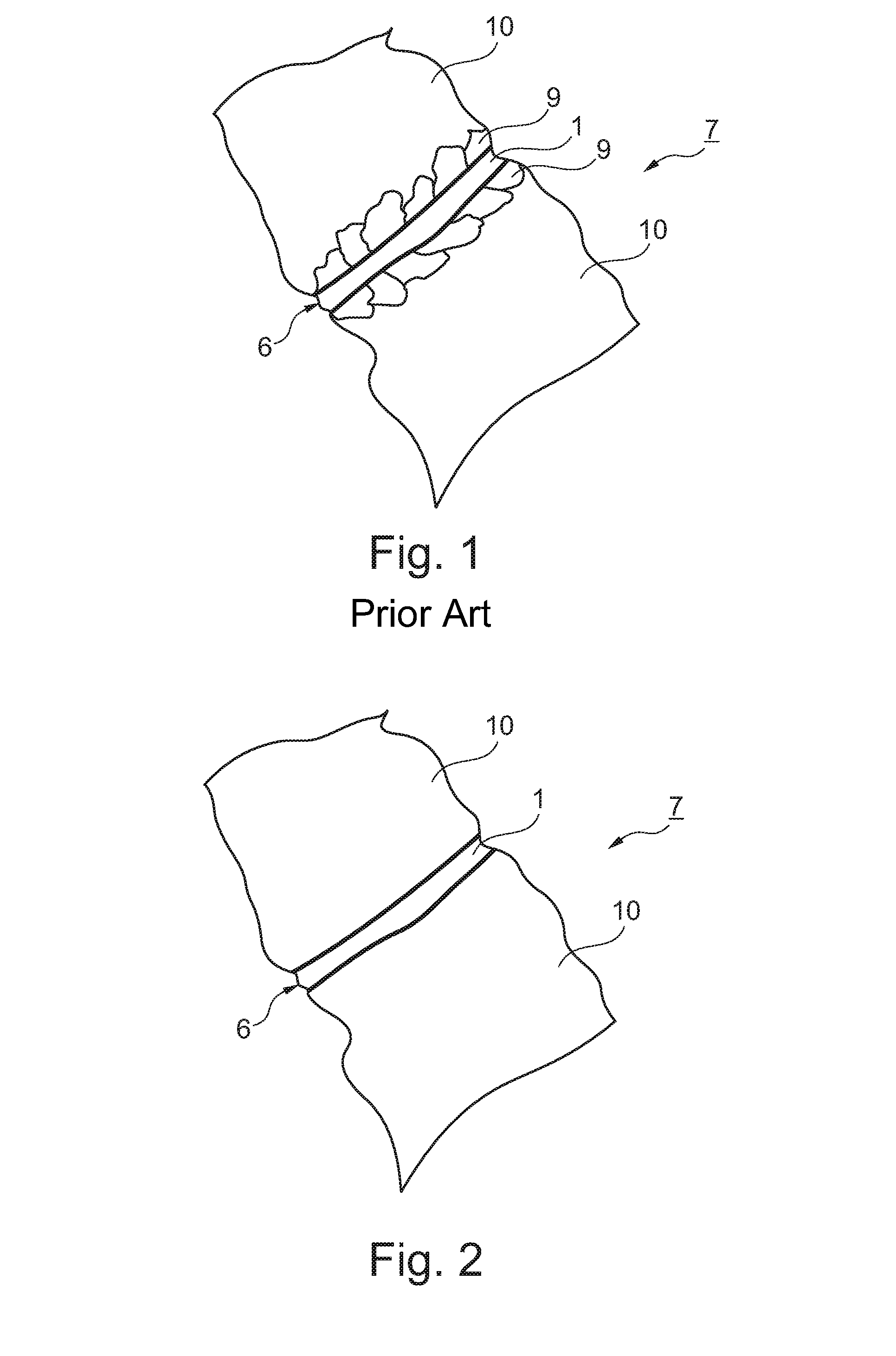
[0045]FIG. 1 schematically shows a joint 6 for repairing a damaged component 7 after a conventional brazing repair method according to the prior art. In the present case, the component 7 is a gas turbine blade or vane made of a single crystal base material 10, to be precise CMSX4 (10% by weight Co, 6.5% by weight Cr, 6.5% by weight Ta, 6% by weight W, 5.6% by weight Al, 2.9% by weight Re, 1% by weight Ti, 0.6% by weight Mo, 0.1% by weight Hf, remainder Ni). The joint 6 was repaired using a conventional braze foil 1, which was produced with the aid of a conventional melt-spin process known from the prior art. The chemical composition of the braze material was the following: 15% by weight Cr, 7.25% by weight Si, 1.4% by weight B, ≦0.06% by weight C, remainder Ni. FIG. 1 clearly shows the recrystallization region 9 around the gap to be brazed 6, where there ...


PUM

PropertyMeasurementUnit
particle sizeaaaaaaaaaa
temperaturesaaaaaaaaaa

Abstract

An amorphous braze foil (1) produced by a melt-spin process has an upper side and a lower side. The upper side and the lower side are thinly coated with a film of metallic Ni-based, Co-based, or Ni—Co-based braze powder (2) with a particle size in the nanometer range, wherein both the braze foil (1) and also the braze powder (2) additionally include grain boundary stabilizing elements as alloying elements. In addition, melting point depressants can be present in the braze foil or in the nano braze powder (2) in a commercially common quantity or with a considerably increased proportion. With the braze foil (1) coated in this manner, both the melting temperature of the braze material and also the probability of recrystallization are advantageously reduced when brazing in the adjacent base material (10).

Description

[0001]This application claims priority to Swiss application no. 01204 / 11, filed 19 Jul. 2011, the entirety of which is incorporated by reference herein.BACKGROUND[0002]1. Field of Endeavor[0003]The invention concerns the field of materials science. It relates to an amorphous braze foil produced by a melt-spin process for high-temperature brazing and to a method for connecting at least two component elements made of single crystal or directionally solidified superalloys for the purpose of producing or repairing components, in particular gas turbine blades or vanes, using a braze foil.[0004]2. Brief Description of the Related Art[0005]At very high loading temperatures, single crystal or directionally solidified components made of superalloys, for example nickel-based, cobalt-based, or nickel-cobalt-based superalloys, have, inter alia, good material strength but also good corrosion resistance and good oxidation resistance as well as good creep strength. On account of this combination o...

Claims


Application Information

Patent Timeline
Patent Type & Authority Patents(United States)
IPC IPC(8): B23K31/02B23K35/14B23P6/04
CPCB23K1/0018B23K35/0233B23K35/3033B23K35/3046Y10T29/49318B23K2201/001F05D2230/237B23K35/30B23K35/0222B23K35/0238B23K35/0244B23K2101/001B23K35/24F01D25/28F02C7/00
Inventor STANKOWSKI, ALEXANDERBECKEL, DANIEL
Owner ANSALDO ENERGIA IP UK LTD
Why Eureka
Try Eureka