Method, equipment and specific drawer for membrane separation utilizing concentration polarization

a concentration polarization and concentration filter technology, applied in the direction of machines/engines, chemical/physical processes, water/sewage treatment by ion exchange, etc., can solve the problems of aggravated membrane fouling, reduced membrane flux, and increased membrane fouling, so as to reduce retention components and enhance filtration efficiency. , the effect of effective control of membrane fouling

Active Publication Date: 2012-08-28
INST OF PROCESS ENG CHINESE ACAD OF SCI
View PDF13 Cites 1 Cited by
  • Summary
  • Abstract
  • Description
  • Claims
  • Application Information

AI Technical Summary

Benefits of technology

[0087](1) By utilizing the concentration polarization, a good effect of enriching a solute is obtainable even if the concentration of a solute in bulk phase is relatively low, thereby greatly enhancing the concentration rate and efficiency.
[0088](2) During the concentration process, the concentrated liquid is discharged from the membrane filtration equipment, so that the potential membrane fouling substances together with the concentrated liquid are discharged from the membrane unit, thereby effectively reducing the potentiality of membrane fouling and greatly decreasing the frequency of cleaning membrane. Therefore, the double functions of concentrating solute and slowing membrane fouling are obtained.
[0089](3) The equipment, technology and operation of the membrane concentration of the present invention are simple, and continuous or semi-continuous operation can be realized and the service life of the membrane further increased at the same time.
[0090](4) The concentration process is performed without shearing force or under a low shearing force, thereby largely reducing energy consumption and effectively decreasing the risk of inactivation and denaturation of biomacromolecules caused by shearing force, therefore the method of the present invention is especially suitable for the concentration of shear-sensitive biomacromolecules.
[0073]The membrane separation method and equipment provided by the present invention can be used to concentrate biomacromolecules and organic micromolecules (such as saccharides, organic acids and polypeptides etc.) in order to overcome the shortcomings of the conventional ultrafiltration concentration process, such as severe membrane fouling, easy to inactivate biomacromolecules, frequent cleaning of membrane and difficult to operate continuously. etc.. The method comprises the adjustment of the thickness of concentration polarization layer on membrane surface and the concentration and distribution of solute in the concentration polarization layer by controlling the operation conditions, such as permeation flux, concentration of material liquor, drawing rate and transmembrane pressure etc., to obtain optimal concentration effects. Wherein, the permeation flux of a filtration membrane may range from 1.84×10⁻⁶ m / s to 3.69×10⁻⁵ m / s, the concentration of a material liquor may range from 1.0 mg / L to 1000 mg / L, the drawing rate may depend on the properties of raw material liquor and concentration requirements and be ½ to 1 / 1000 of the flux of raw material liquorfed into the membrane concentration equipment, and the transmembrane pressure may range from 0.01 MPa to 4 MPa.

Problems solved by technology

However, concentration polarization phenomenon generally existing in membrane separation processes is one of main factors affecting membrane flux and causing membrane fouling.
Since concentration polarization not only causes the decrease in membrane flux but also aggravates membrane fouling due to the enriching of retention components on membrane surface, concentration polarization is a problem generally to be solved during membrane separation processes.
However, the methods and equipments for reducing concentration polarization and membrane fouling to maintain membrane flux still need to be developed.

Method used


Image

  • Method, equipment and specific drawer for membrane separation utilizing concentration polarization
  • Method, equipment and specific drawer for membrane separation utilizing concentration polarization
  • Method, equipment and specific drawer for membrane separation utilizing concentration polarization

Examples


example 1

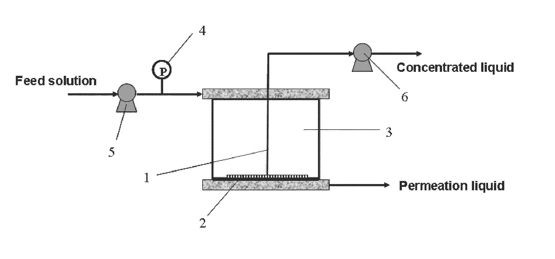
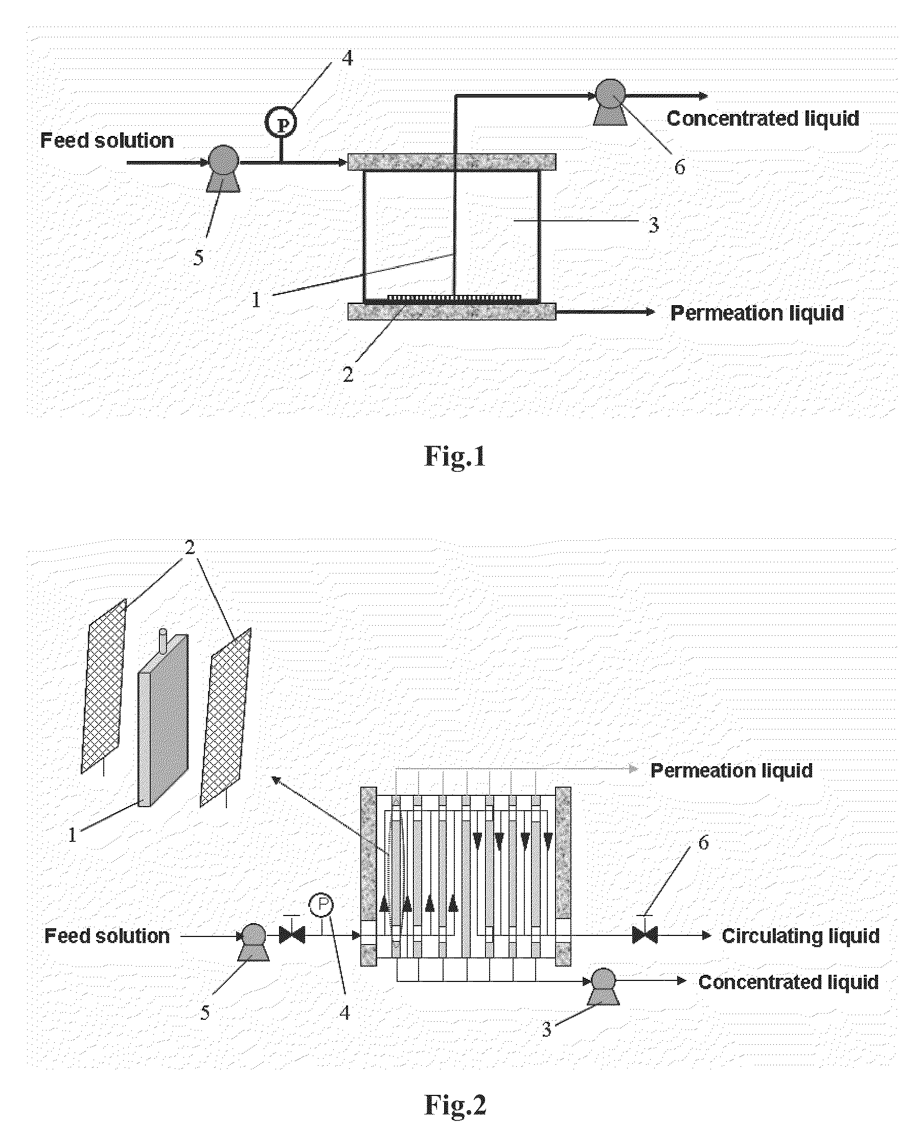
[0101]Turning to FIG. 1, the equipment for a dead-end membrane filtration process of concentrating biomacromolecules and organic micromolecules utilizing concentration polarization comprised: a dead-end filtration cell 3, a filtration membrane 2, a drawer 1 for drawing a concentrated liquid, a pressure sensor 4, a feeding pump 5, and an injection pump or constant flow pump 6.

[0102]The dead-end filtration cell 3 had an effective membrane area of 4.45 cm2 and a volume of 6.7 mL. The tabular filtration membrane 2 was located on the bottom of the dead-end filtration cell, wherein the filtration membrane was Ultracel PL ultrafiltration membrane of regenerated cellulose with a molecular weight cut-off of 10 KD and a high recovery rate (Millipore Company). The drawer 1 made of a hollow plastic or silicone pipe having an external diameter ranging from 0.5 to 1.5 mm was configured on the filtration membrane surface, wherein one end of said drawer extended outside the dead-end filtration cell...

example 2

[0105]The method and equipment used were the same as those in Example 1, while the concentration of BSA in a feed solution (Cf) was 0.5 g / L and the permeation flux (Jv) of the filtration membrane was 3.745×10⁻⁶ m3 / (m2·s). When the TMP increased to 100 KPa and 150 KPa, the concentrated liquid was drawn at a drawing rate of 360 μL / h and 420 μL / h, respectively. At the initial stage of drawing, the TMP under both experimental conditions decreased, and then it could be stabilized at 60 and 107 KPa for a long period of time, respectively, suggesting that membrane fouling was effectively controlled during concentration process and the concentration operation could be stably conducted for a long period of time. After operation for 8 hours, the average concentrations of BSA in the concentrated liquids obtained by drawing were 8.9 and 7.0 g / l, i.e., 17.8 and 14.0 times as that in the feed, respectively.

example 3

[0106]The method and equipment used were the same as those in Example 1, while the concentration of BSA in a feed solution (Cf) was 0.5 g / L and the permeation flux (Jv) of the filtration membrane was 3.745×10⁻⁶ m3 / (m2·s). In order to obtain a concentrated liquid with a higher concentration, an intermittent drawing mode was used to draw the concentrated liquid. The drawing operation started up at a TMP of 100 and 150 KPa and a drawing rate of 360 μL / h and 420 μL / h, respectively. Such operation stopped when the TMP decreased to 60 and 107 KPa respectively. When the TMP again reached the values for initiating the drawing, the concentrated liquid was drawn at the same rates again. The above operations were conducted repeatedly. After operation for 8 hours, the concentrations of BSA in the concentrated liquid obtained by the drawing were 11.8 and 12.4 g / l, i.e., 23.6 and 24.8 times as that in the feed, respectively. Clearly, the multiple intermittent drawing operation mode facilitates th...


PUM

PropertyMeasurementUnit
sizeaaaaaaaaaa
sizeaaaaaaaaaa
sizeaaaaaaaaaa

Abstract

The present invention relates to a membrane separation method and a relevant equipment, in particular to a method and an equipment for membrane separation utilizing concentration polarization during membrane filtration process, especially, to a concentration process and equipment and a drawer special for drawing a concentration polarization layer. The direct removal of the concentration polarization layer from membrane surface not only decreases the adverse influence of concentration polarization on membrane separation but also obtains concentrated retention components, thereby significantly improving the ability to maintain membrane flux, solving the twinborn problems concerning concentration polarization and membrane fouling during the membrane separation process, and achieving a high-efficiency concentration for retention components. The method and equipment of the present invention can be widely applied in various membrane techniques, in particular in a membrane separation process for concentrating biomacromolecule and organic micromolecule products such as sugars, organic acids and polypeptides etc.

Description

TECHNICAL FIELD[0001]The present invention relates to a method and equipment for membrane separation, in particular to a method and equipment as well as a specific drawer for the separation utilizing concentration polarization during membrane separation processes.BACKGROUND ART[0002]Membrane separation refers to a method for separation, concentration and purification of a raw material by using a selective permeation membrane, in which the components of the raw material at the side of raw material selectively permeate the membrane when there exists a certain driving force (such as pressure difference, concentration difference, potential difference or temperature difference etc.). Different membranes and driving forces are employed in different membrane separation processes. At present, the membrane separation processes that have been industrially used include microfiltration (MF), ultrafiltration (UF), reverse osmosis (RO), dialysis (D), electrodialysis (ED), gas separation (GS), per...

Claims


Application Information

Patent Timeline
Patent Type & Authority Patents(United States)
IPC IPC(8): B01D29/075B01D33/44
CPCB01D61/145B01D61/147B01D63/082B01D65/08B01D2321/26B01D63/0822
Inventor WAN, YINHUACHEN, XIANGRONGSU, ZHIGUOMA, GUANGHUIJIAO, XIAOGUANGSHEN, FEICUI, ZHANFENG
Owner INST OF PROCESS ENG CHINESE ACAD OF SCI
Why Eureka
Try Eureka