Light emitting device and electronic device utilizing fibrous barrier layers impregnated with organic resin
a technology of organic resin and light-emitting device, which is applied in the manufacture of electrode systems, electric discharge tubes/lamps, discharge tubes luminescnet screens, etc., to achieve high yield, prevent defects of shape and characteristics, and high reliability
- Summary
- Abstract
- Description
- Claims
- Application Information
AI Technical Summary
Benefits of technology
Problems solved by technology
Method used
Image
Examples
embodiment 1
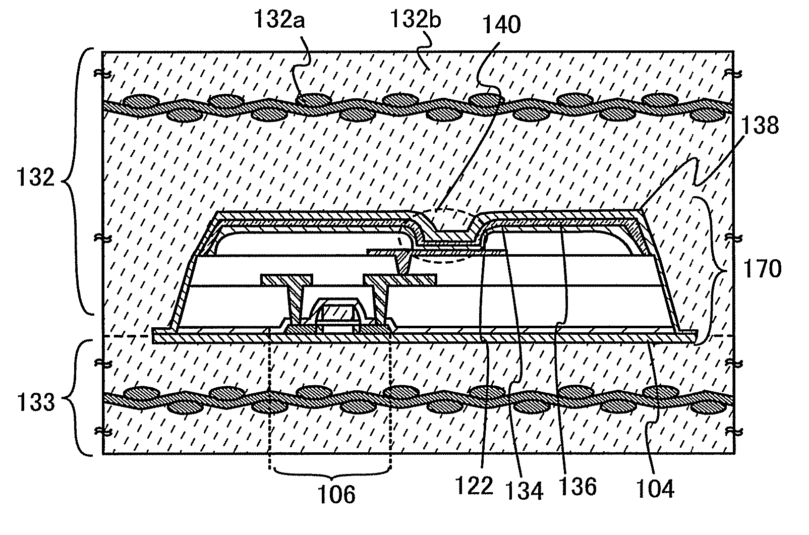
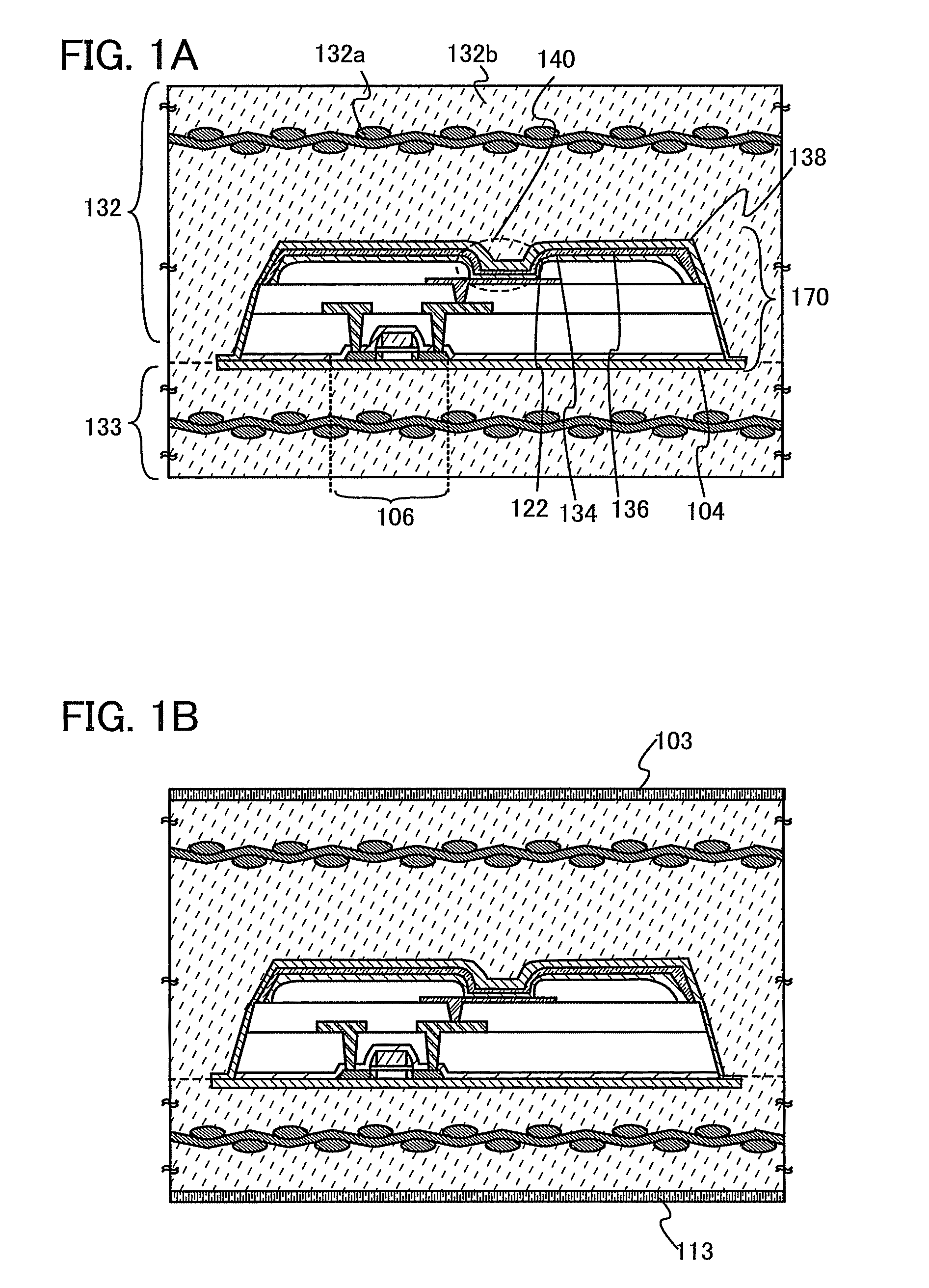
[0038]In this embodiment, an example of a light emitting device which is one embodiment of the present invention will be described in detail with reference to FIGS. 1A and 1B.
[0039]A display portion of a light emitting device of this embodiment is illustrated in FIGS. 1A and 1B. The light emitting device of this embodiment illustrated in FIG. 1A has an element portion 170 sealed between a first structure body 132 and a second structure body 133. In addition, an insulating layer 104 and an insulating layer 138 are formed between the element portion 170 and the second structure body 133 and between the element portion 170 and the first structure body 132. The first structure body 132 and the second structure body 133 are each a structure body in which a fibrous body 132a is impregnated with an organic resin 132b. In addition, the first structure body 132 and the second structure body 133 are in contact with each other and fixed to each other in a region where the element portion 170 i...
embodiment 2
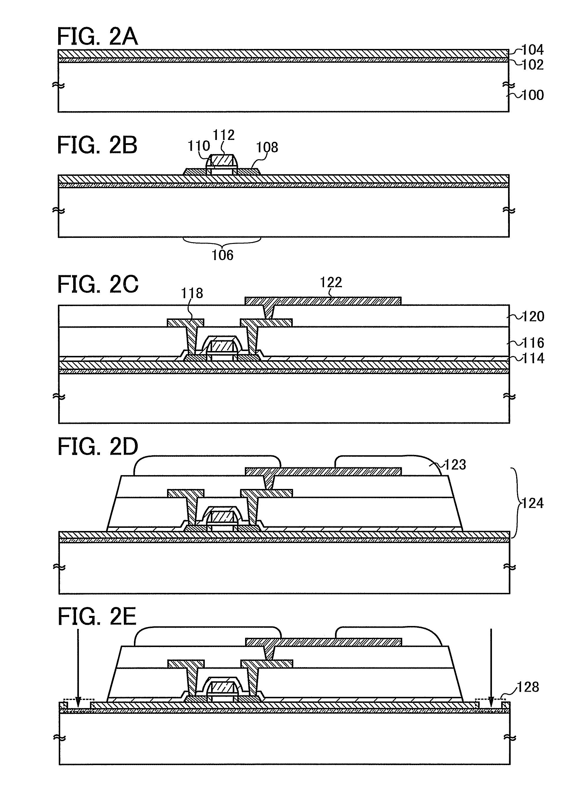
[0058]In this embodiment, an example of a method for manufacturing a light emitting device illustrated in FIG. 1A will be described in detail with reference to FIGS. 2A to 2E, FIGS. 3A to 3C, and FIGS. 4A to 4C.
[0059]First, a separation layer 102 is formed on a surface of a substrate 100; successively, the insulating layer 104 is formed (see FIG. 2A). The separation layer 102 and the insulating layer 104 can be formed in succession. By forming successively, they are not exposed to the air so that impurities can be prevented from being contained therein.
[0060]For the substrate 100, a glass substrate, a quartz substrate, a metal substrate, a stainless steel substrate, or the like may be used. For example, when a rectangular glass substrate with a side of one meter or more is used, productivity can be drastically improved.
[0061]Note that in this process, the case where the separation layer 102 is provided on the entire surface of the substrate 100 is described; however, the separation ...
embodiment 3
[0111]In this embodiment, an example of a method for manufacturing a light emitting device different from that of the aforementioned embodiment will be described with reference to drawings. Note that in this embodiment, a manufacturing process of the light emitting device illustrated in FIG. 1A is described as an example.
[0112]First, the separation layer 102 is formed over one surface of the substrate 100, and the insulating layer 104 is successively formed. Then, a first electrode 150 is formed over the insulating layer 104 (see FIG. 5A).
[0113]Note that the first electrode 150 is an electrode that is used as an anode or a cathode of a light emitting element. In the case of being used as the anode, a material having a high work function is preferably used. For example, a single-layer film such as an indium tin oxide film, an indium tin oxide film containing silicon, a light-transmitting conductive film formed by a sputtering method using a target in which indium oxide is mixed with ...
PUM
 Abstract
Description
Claims
Application Information
 - R&D
- Intellectual Property
- Life Sciences
- Materials
- Tech Scout
- Unparalleled Data Quality
- Higher Quality Content
- 60% Fewer Hallucinations
Browse by: Latest US Patents, China's latest patents, Technical Efficacy Thesaurus, Application Domain, Technology Topic, Popular Technical Reports.
© 2025 PatSnap. All rights reserved.Legal|Privacy policy|Modern Slavery Act Transparency Statement|Sitemap|About US| Contact US: help@patsnap.com


