

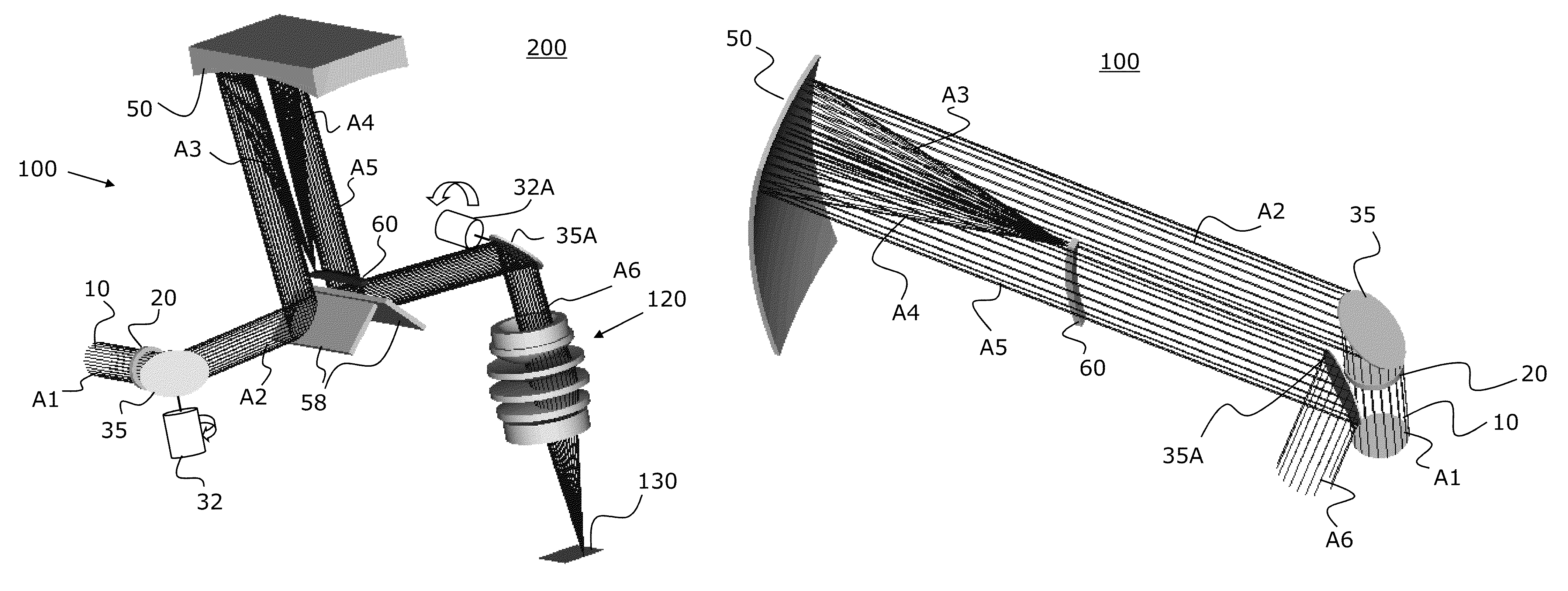
Concentric afocal beam relay
a beam relay and afocal beam technology, applied in the field of beam steering and scanning systems, can solve the problems of reducing the efficiency of beam scanning, and reducing the accuracy of beam scanning, so as to reduce the third-order aberration of concentric reflective optical designs, reduce the effect of pupil size and large deflection angl
- Summary
- Abstract
- Description
- Claims
- Application Information
AI Technical Summary
Benefits of technology
Problems solved by technology
Method used
Image

Examples
Embodiment Construction
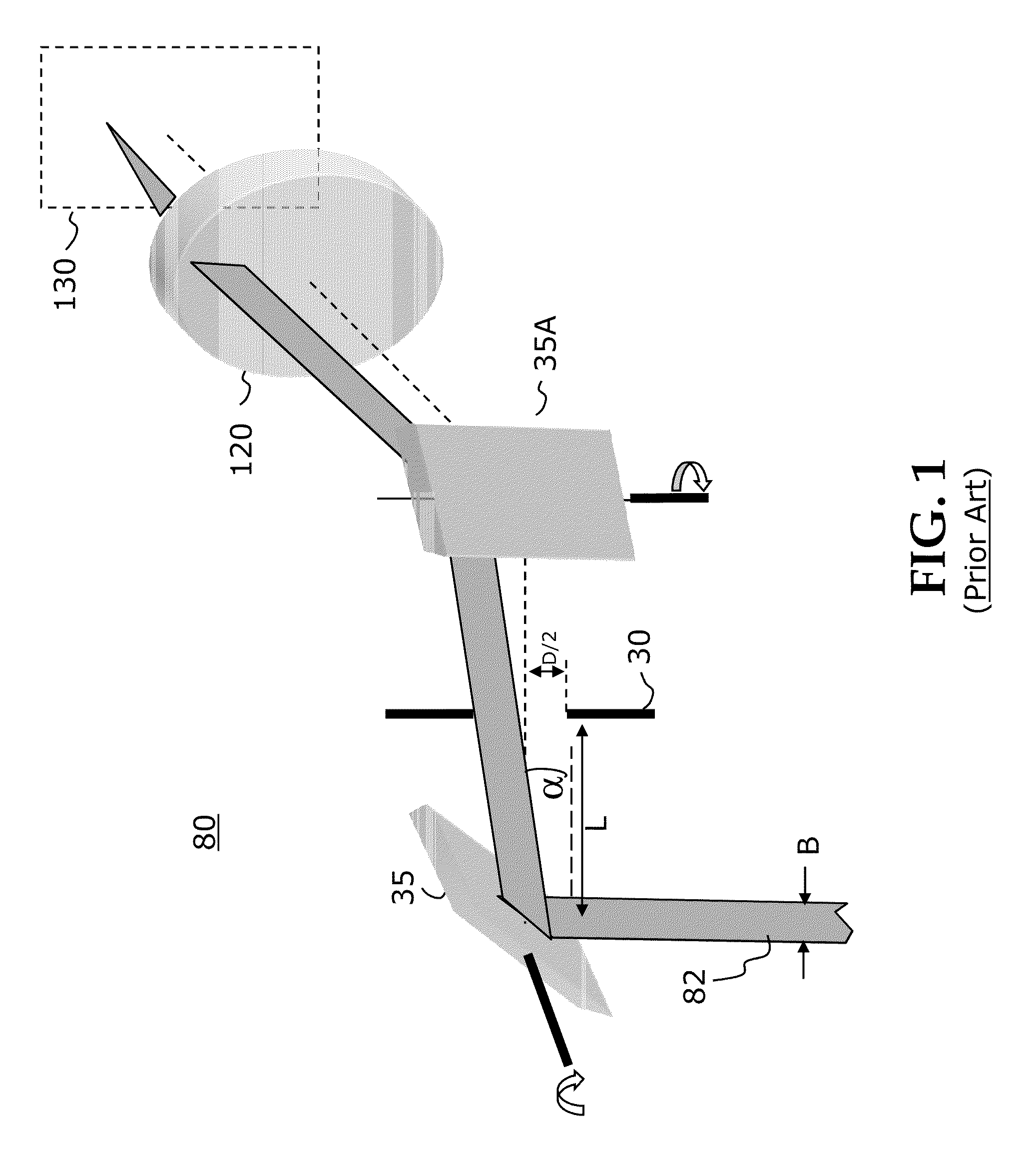
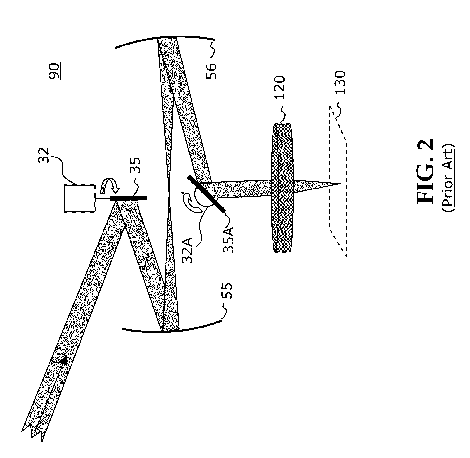
[0050]The following is a detailed description of preferred, but non-limiting, embodiments of the invention, reference being made to the drawings in which the same reference numerals identify the same elements of structure in each of the several figures. It is to be understood that elements not specifically shown or described may take various forms well known to those skilled in the art. For example, conventional scanning optical systems are well known in the optical arts and are not, therefore, described in detail herein, except for those parts of systems related either directly to embodiments of the present invention or cooperating in some way with embodiments of the present invention.
[0051]Figures shown and described herein are provided in order to illustrate key principles of operation and component relationships along their respective optical paths according to the present invention and are not drawn with intent to show actual size or scale. Some exaggeration may be necessary in...
PUM
 Abstract
Description
Claims
Application Information