Synchronized power supply for medical imaging

a power supply and medical imaging technology, applied in the field of medical imaging system and method, can solve problems such as image degradation, interference pattern, modulation of echoed signals received from burst to burst, etc., and achieve the effect of reducing the size and weight of the ultrasound system

Active Publication Date: 2012-10-16
SONOWISE
View PDF64 Cites 10 Cited by
  • Summary
  • Abstract
  • Description
  • Claims
  • Application Information

AI Technical Summary

Benefits of technology

[0011]It is an aspect of the present invention to provide an improved ultrasound imaging system and method with a programmable and synchronized clock thus without requiring a linear voltage regulator for interference reduction. The embodiment of this invention can significantly reduce the size and weight of the ultrasound system thus enabling a person of ordinary skill to overcome the above-discussed difficulties.
[0012]In yet another aspect, the present invention further provides an improved ultrasound imaging system and method with a programmable and synchronized clock for the high voltage switching power supply to substantially eliminate the interference due to the switching noise and its harmonics.
[0013]In yet another aspect, the present invention provides a method for the high voltage switcher of an ultrasound system to generate the output that can be optionally put through a conventional linear regulator to further reduce noise ripple and allow the final high voltage output to be programmed by the system controller in various scan modes.

Problems solved by technology

Even though there are significant advancements made in the ultrasound scanning technologies for scanning biological objects to carry out medical image and diagnostic tasks, there are still technical difficulties caused by signal interferences that lead to image degradations.
However, the echoed signals received from burst to burst are modulated due to the interferences caused by the switching operations of the high voltage power supply interference, e.g., the outgoing burst signals are interrupted by the switching noises thus affecting the echo signals.
A two-dimensional scanned image reflected back from the biological tissues thus presents an interference pattern due to these interferences.
Furthermore, the interferences also cause the Doppler spectrum to present extra inter-modulation tones.
The isolation transformer commonly implemented in an ultrasound system is heavy and bulky and also are operated with very low efficiency (e.g. less than 60%).
Such configuration and circuit implementation however generate a technical difficulty that the DC voltages generated from the free running switching clock create incoherent interferences that affect the receiving echo in many aspects of the system operations.
Furthermore, the free-running switching clock further interferes with the electric circuits in the front-end receiving beam former and in the transducer shielding.
These interferences further degrade the scanned images due to the impacts that these interferences have on the patterns of the two-dimensional images or the inter-mod tones on the Doppler spectrum.
The transformer used in the high voltage linear regulator is heavy and bulky and not suitable for a portable unit.
This new technology increases the power efficiency, reduce the component size, but will create a big challenge in shielding the interference from the switching frequency and its harmonics.
The problem is worse in the highly sensitive all digital front end with color Doppler, pulse (PW) and continuous wave (CW) Doppler functions.
Therefore, the conventional ultrasound systems employed to obtain Doppler and image signals are either bulky or become very vulnerable to the interferences by the high voltage switching noises.
These interference noises can affect the signals receptions either through the radiation propagated in the system or through the conductive path.
Such problems are especially pronounced in the portable color Doppler units due to the very limit space of such device.
Special designs to provide layout to shield such interferences become a highly difficult task.
The portability of a color Doppler unit is therefore greatly limited.

Method used


Image

  • Synchronized power supply for medical imaging
  • Synchronized power supply for medical imaging
  • Synchronized power supply for medical imaging

Examples


Embodiment Construction

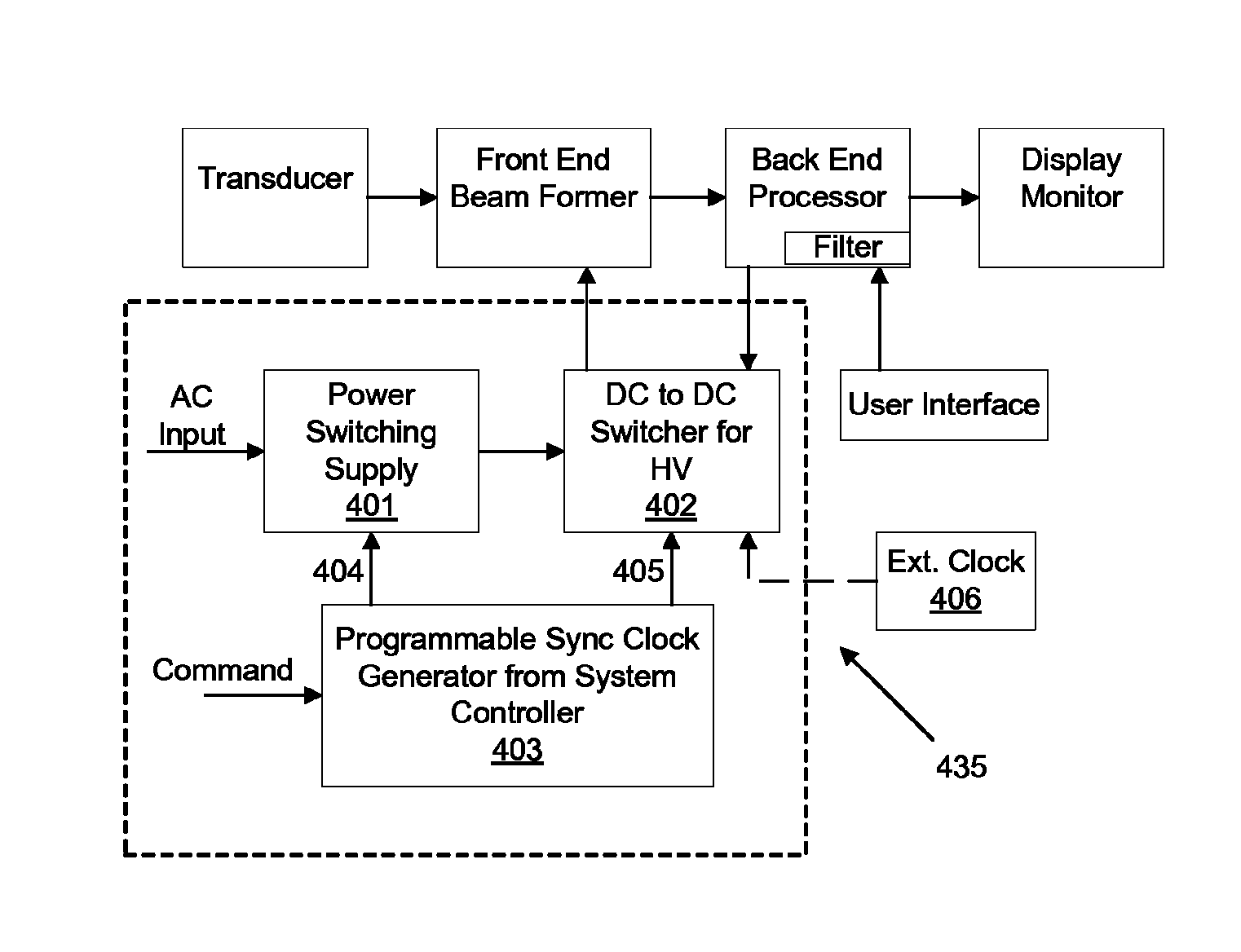
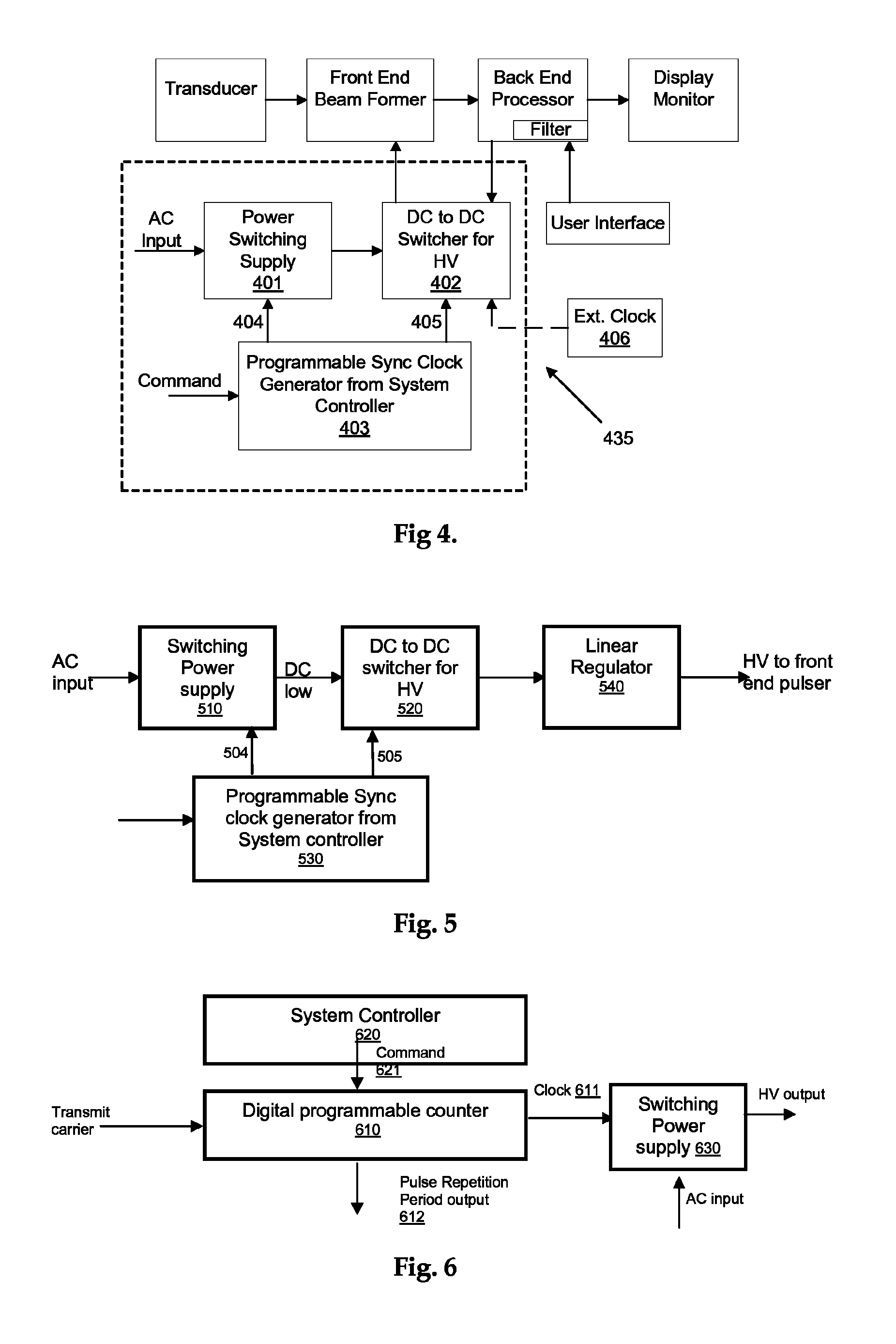
[0023]Referring to FIG. 4 for an embodiment of a voltage generator 435 of the present invention. The voltage generator includes a switching power supply 401 for generating a DC low voltage, and DC-to-DC switcher 402 for generating high voltage. The switching power-supply 401 and the DC-to-DC switching high voltage generator 402 are both connected to a programmable, sync clock generator 403. The 403 is further controlled by a system controller (not shown) to set up the synchronized clock signals 404 and 405 to the switching power supply 401 and the DC-to-DC switch high voltage generator 402 respectively. The low voltage outputs from 401 also provide low voltages, e.g., +3.3, +5, +12V, for the digital circuitry. The digital circuitry normally has higher interference immunity; therefore the implementation of an external synchronization clock 406 can be optional when the digital circuits are shielded properly.

[0024]The programmable synchronization clock generator 403 is connected to the...


PUM


Abstract

An ultrasonic image scanning system for scanning an organic object by projecting ultrasound signals with a transmit carrier frequency. The ultrasonic image scanning system includes a switching mode power supply operated with a programmable clock in synchronization with the transmit carrier frequency. The switching mode power supply further provided with circuits for generating a low voltage and a high voltage. The ultrasonic image scanning system further includes transducers for projecting ultrasound signals wherein the transducers are connected to and electrically excited by the high voltage generated by the switching mode power supply. The switching mode power supply further includes a DC-to-DC switcher having an external clock input for clock synchronization. The programmable clock further provided for receiving a user command to operate with the switching mode power supply in synchronization with the transmit carrier frequency

Description

[0001]This Application is a Formal Application and claims a Priority Filing Date of Oct. 30, 2004 benefited from a previously filed Application No. 60 / 623,729 filed previously by the inventor of this Patent Application.FIELD OF THE INVENTION[0002]This invention generally relates to system and method for carrying out a medical imaging process. More particularly, this invention relates to an improved power supply system implemented with a programmable clock synchronization signal generator controlled by a system controller to minimize signal interferences generated by different switching, pulsing and modulation circuits when running with free running clocks.BACKGROUND OF THE INVENTION[0003]Even though there are significant advancements made in the ultrasound scanning technologies for scanning biological objects to carry out medical image and diagnostic tasks, there are still technical difficulties caused by signal interferences that lead to image degradations.[0004]Specifically, durin...

Claims


Application Information

Patent Timeline
Patent Type & Authority Patents(United States)
IPC IPC(8): A61B8/00
CPCG01S7/52017G01S7/5205A61B8/56H02M1/12G01S7/52077
Inventor PHUNG, HUE
Owner SONOWISE
Why Eureka
Try Eureka