
Catalyst life improvement for the vapor phase manufacture of 1-chloro-3,3,3-trifluoropropene

a technology of trifluoropropene and catalyst, which is applied in the preparation of halogenated hydrocarbons, physical/chemical process catalysts, hydrogen halide split-off, etc., can solve the problems of short catalyst life in comparison to other fluorination reactions, etc., and achieves the effect of reducing the loss of production time, increasing catalyst life, and slowing down catalyst deactivation

Active Publication Date: 2012-10-23
HONEYWELL INT INC
View PDF11 Cites 2 Cited by
  • Summary
  • Abstract
  • Description
  • Claims
  • Application Information

AI Technical Summary

Benefits of technology

[0012]In one embodiment of the invention, chromium oxide catalyst life during fluorination of HCC-240fa with HF to produce HCFO-1233zd(E) is significantly increased (i.e., a minimum two fold increase of catalyst life) when an oxygen co-feed is introduced into the fluorination reactor with the feeds of the raw materials, HCC-240fa and HF. This is advantageous because a slower catalyst deactivation by including an oxygen co-feed minimizes the loss in production time due to the need to regenerate the catalyst off-line. The source of oxygen can be oxygen gas, dry air, or oxygen gas diluted with inert gas such as nitrogen, argon, or helium.
[0013]Accordingly, one embodiment of the present invention is a method of extending the lifetime of a catalyst used in the vapor phase catalytic fluorination reaction of the raw materials 1,1,1,3,3-pentachloropropane (HCC-240fa) and hydrogen fluoride (HF) to produce 1-chloro-3,3,3-trifluoropropene, wherein the catalyst life is extended by at least two-fold, by introducing an oxygen co-feed into the fluorination reaction.
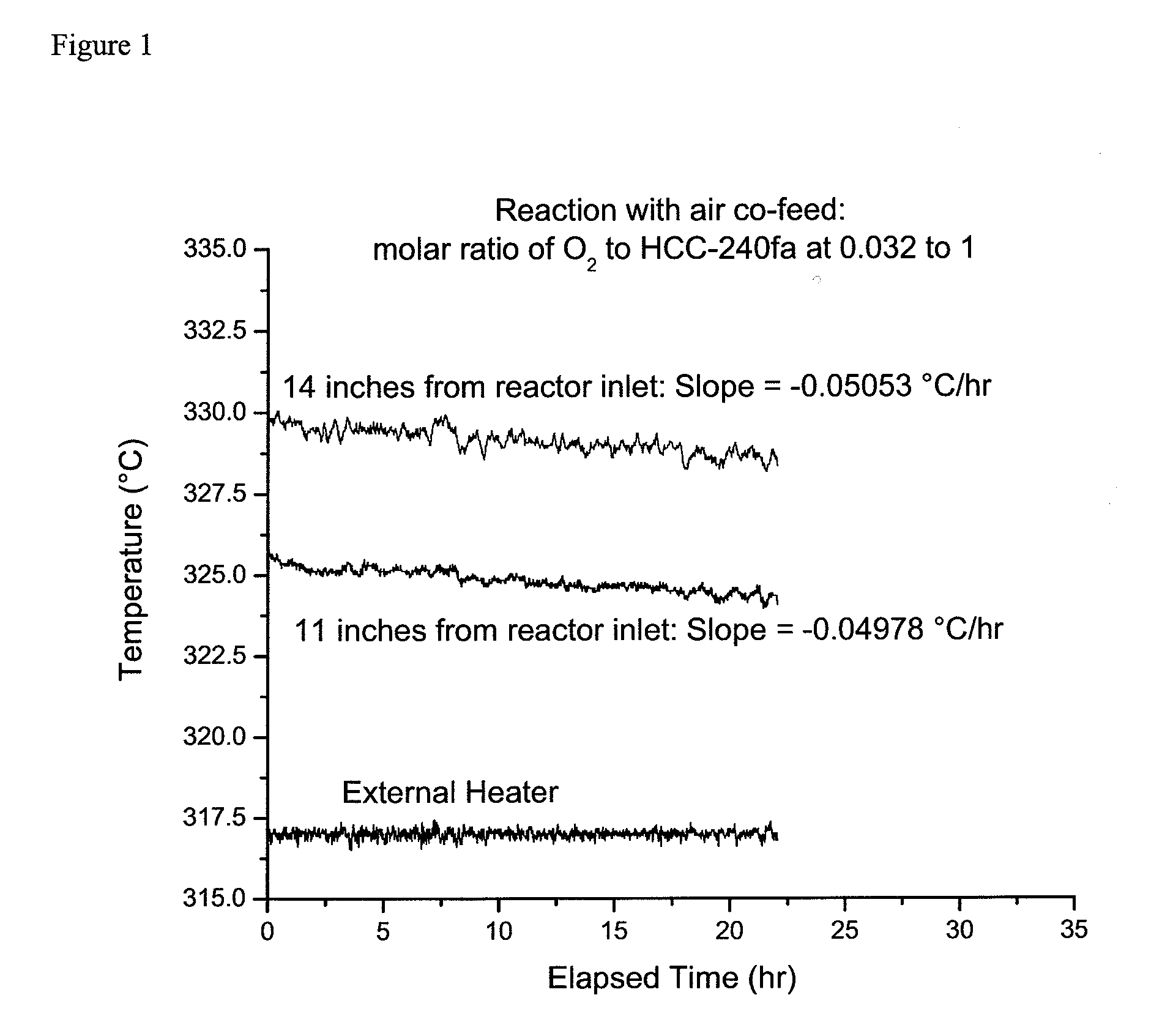
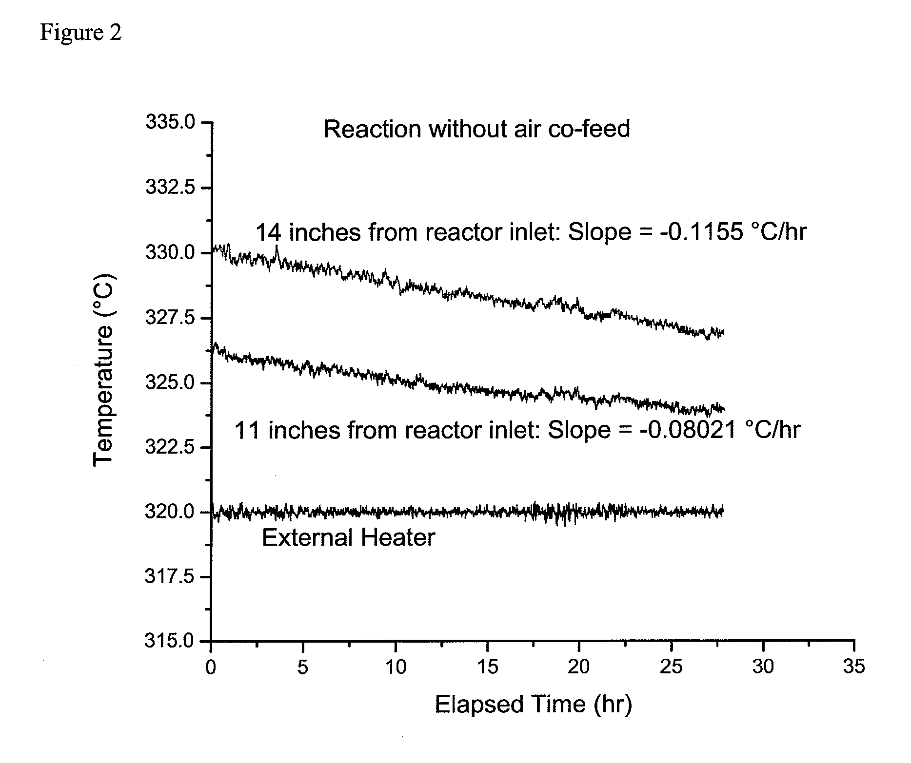
[0014]The reaction of HCC-240fa with HF to form HCFO-1233zd is an exothermic reaction. The present inventors have further discovered a correlation between the rate of catalyst deactivation during the reaction of HCC-240fa with HF and the rate of the temperature change inside the catalyst bed. In addition, an active catalyst exhibits a large exotherm relative to the external reactor heater. As the catalyst deactivates, the exotherm diminishes, and the temperature inside the deactivated catalyst bed approaches that of the external heater. Monitoring this change in the exotherm allows the reactor operator to add the oxygen co-feed to the reactor feed, to keep the catalyst from being deactivated for a longer period of time.
[0015]Accordingly, another embodiment of the present invention is a method of extending the lifetime of a catalyst used in the vapor phase catalytic fluorination reaction of the raw materials 1,1,1,3,3-pentachloropropane (HCC-240fa) and hydrogen fluoride (HF) to produce 1-chloro-3,3,3-trifluoropropene, wherein the catalyst life is extended by monitoring the exotherm of the active catalyst relative to the external reactor heater, and adding an oxygen co-feed into the fluorination reaction to keep the catalyst from being deactivated for up to two-times longer than when no oxygen co-feed is employed.

Problems solved by technology

During initial reaction studies it was discovered that the catalyst life was very short in comparison to other fluorination reactions that incorporate the same catalyst.
However, this method for regeneration of the catalyst requires the shut down of the reactor, resulting in a loss of production time.

Method used


Image

  • Catalyst life improvement for the vapor phase manufacture of 1-chloro-3,3,3-trifluoropropene
  • Catalyst life improvement for the vapor phase manufacture of 1-chloro-3,3,3-trifluoropropene
  • Catalyst life improvement for the vapor phase manufacture of 1-chloro-3,3,3-trifluoropropene

Examples


example 1

[0037]This example illustrates the continuous vapor phase fluorination reaction of 1,1,1,3,3-pentachloropropane with hydrogen fluoride to form 1-chloro-3,3,3-trifluoropropene and hydrogen chloride in the presence of oxygen co-feed. The fluorination catalyst for the experiment was fluorinated Cr2O3.

HCC-240fa+3HF→1233zd+4HCl

[0038]A continuous vapor phase fluorination reaction system consisting of air, N2, HF, and organic feed systems, feed vaporizer, superheater, two-inch inner diameter monel reactor, acid scrubber, drier, and product collection system was used. The reactor was loaded with 2135 grams of fluorinated Cr2O3 catalyst which equates to about 1.44 liters of catalyst (the total height of the catalyst bed was about 28 inches). A multipoint thermocouple was installed in the middle of the reactor. The reactor was then heated to a reaction temperature of about 275° C. with a nitrogen gas (N2) purge going over the catalyst after the reactor had been installed in a constant tempera...

example 2

[0043]This example is a comparative example intended to illustrate the effect of oxygen co-feed on the chromium oxide catalyst stability during the continuous vapor phase fluorination reaction of 1,1,1,3,3-pentachloropropane with hydrogen fluoride to produce 1-chloro-3,3,3-trifluoropropene and hydrogen chloride.

HCC-240fa+3HF→1233zd+4HCl

[0044]For this example the same reaction system and reaction conditions were used as in the Example 1 with the exception that at the completion of the experiment for Example 1, the air co-feed was stopped.

[0045]After the air co-feed was stopped the temperature of the external heater was adjusted to bring the catalyst bed temperature, 14 inches from the reactor inlet, to about 330° C. Then, as in Example 1, and as shown in FIG. 2, the catalyst bed temperatures at positions 11 and 14 inches from the reactor inlet were monitored for over 20 hours. It was calculated that the temperature at 11 inches was decreasing linearly at the rate of 0.08021° C. / hr an...


PUM

PropertyMeasurementUnit
molar ratioaaaaaaaaaa

Abstract

This invention achieves a catalyst life improvement for the catalyzed vapor phase reaction of 1,1,1,3,3-pentachloropropane with hydrogen fluoride to form 1-chloro-3,3,3-trifluoropropene by introducing an oxygen co-feed into the fluorination reactor. By introduction of an oxygen co-feed to the reactor feed, the catalyst life was extended a minimum of two-fold (2×).

Description

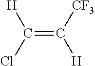
BACKGROUND OF THE INVENTION[0001]The compound E-1-chloro-3,3,3-trifluoropropene (HCFO-1233zd(E)) is a next generation liquid low global warming potential (LGWP) foam blowing agent, refrigerant and solvent. This compound has the following structure:[0002][0003]HCFO-1233zd(E) is a known compound. It can be produced in a vapor phase reaction as taught in U.S. Pat. No. 5,710,352; or it can be produced in a liquid phase reaction as taught in U.S. Pat. No. 6,844,475. These patents are hereby incorporated herein by reference in their entirety.[0004]The deactivation of chromium oxide catalyst during fluorination of HCC-240fa is described in U.S. Pat. No. 5,710,352. According to U.S. Pat. No. 5,811,603, catalyst stability during the vapor phase fluorination of 1,1,3,3-tetrachloropropene (HCFO-1230za) with HF to produce 1,1,1,3,3-pentafluoropropane and 1-chloro-3,3,3-trifluoropropene can be improved by co-feeding oxygen or chlorine into the reactor.[0005]The use of chlorofluorocarbons and hyd...

Claims


Application Information

Patent Timeline
Patent Type & Authority Patents(United States)
IPC IPC(8): C07C17/00
CPCC07C17/25C07C21/18B01J38/12B01J27/128B01J27/132Y02P20/584
Inventor MERKEL, DANIEL C.POKROVSKI, KONSTANTIN A.TUNG, HSUEH SUNG
Owner HONEYWELL INT INC
Learn More