Multi-fuelling an engine

a multi-fuelling, compression ignition technology, applied in the direction of machines/engines, oscillatory slide valves, electric control, etc., can solve the problems of increased knock susceptibility, increased ignition delay, increased nitrous oxide (nosub>x/sub>), etc., to reduce nox and soot emissions

Inactive Publication Date: 2012-12-11
G VOLUTION
View PDF5 Cites 16 Cited by
  • Summary
  • Abstract
  • Description
  • Claims
  • Application Information

AI Technical Summary

Benefits of technology

[0007]A method according to the invention comprises supplying a first fuel to a combustion chamber of the engine and injecting a second fuel into the combustion chamber; characterised in that the first fuel comprises a volatile liquid or combustible gas; the second fuel comprises diesel or biodiesel; and the second fuel is injected in multiple pulses in each ignition cycle with the first pulse acting as a pilot pulse to trigger ignition, and the timing of the second pulse being such as to modify the temperature through evaporation of the second fuel and thereby reduce the combustion temperature and mitigate knock susceptibility.
[0008]The pilot pulse needs to inject sufficient of the second fuel to ignite the mixture reliably at all loads and to generate a high enough temperature to vaporise the second pulse when it is injected. Too little pilot fuel will cause cycle-to-cycle combustion variability and even misfiring, but too much pilot fuel will lead to increased knock susceptibility, nitrous oxide (NOx) emissions, and increased ignition delay. Ignition delay also increases with the quantity of the first fuel added.
[0011]As regards injection of further pulses of fuel after the second pulse, this is possible to increase the quantity of fuel injected. The effect of third or fourth pulses on knock and NOx is only slight, but soot emissions increase. A pilot pulse followed by a single further pulse or main pulse is the preferred operating mode to optimise NOx and soot emissions.
[0012]A further benefit of the invention is that when the first fuel is a bio fuel, such as bioethanol, the operation of the engine is relatively tolerant to the water content of the bio fuel, and this allows use of bio fuel which has not been dehydrated and has therefore a lower production cost. The effect of the water content requires more fuel to be injected for the equivalent energy content, and the amount of fuel injected in the pilot pulse needs to be increased to ensure ignition of the mixture. The effect on knock and NOx, if anything, is to improve them. The only adverse effect is in slightly increased soot emissions.
[0014]In one embodiment of the invention, the engine may be controlled to operate in two different modes, one mode for light and medium load conditions when there is only a pilot pulse injection of the second fuel which reduces NOx and soot emissions, and the other mode for higher load conditions when there is a pilot pulse injection followed by a main pulse injection of the second fuel.

Problems solved by technology

Too little pilot fuel will cause cycle-to-cycle combustion variability and even misfiring, but too much pilot fuel will lead to increased knock susceptibility, nitrous oxide (NOx) emissions, and increased ignition delay.
Ignition delay also increases with the quantity of the first fuel added.
However, the timing range is quite small.
The second pulse needs to be injected when the combustion chamber temperature is sufficiently high and thus the two pulses need to be appropriately separated for the combustion process to take place; but if the pulses are separated too much then cycle-to-cycle variation in combustion become a problem.

Method used


Image

  • Multi-fuelling an engine
  • Multi-fuelling an engine
  • Multi-fuelling an engine

Examples


Embodiment Construction

1) Experimented Equipment

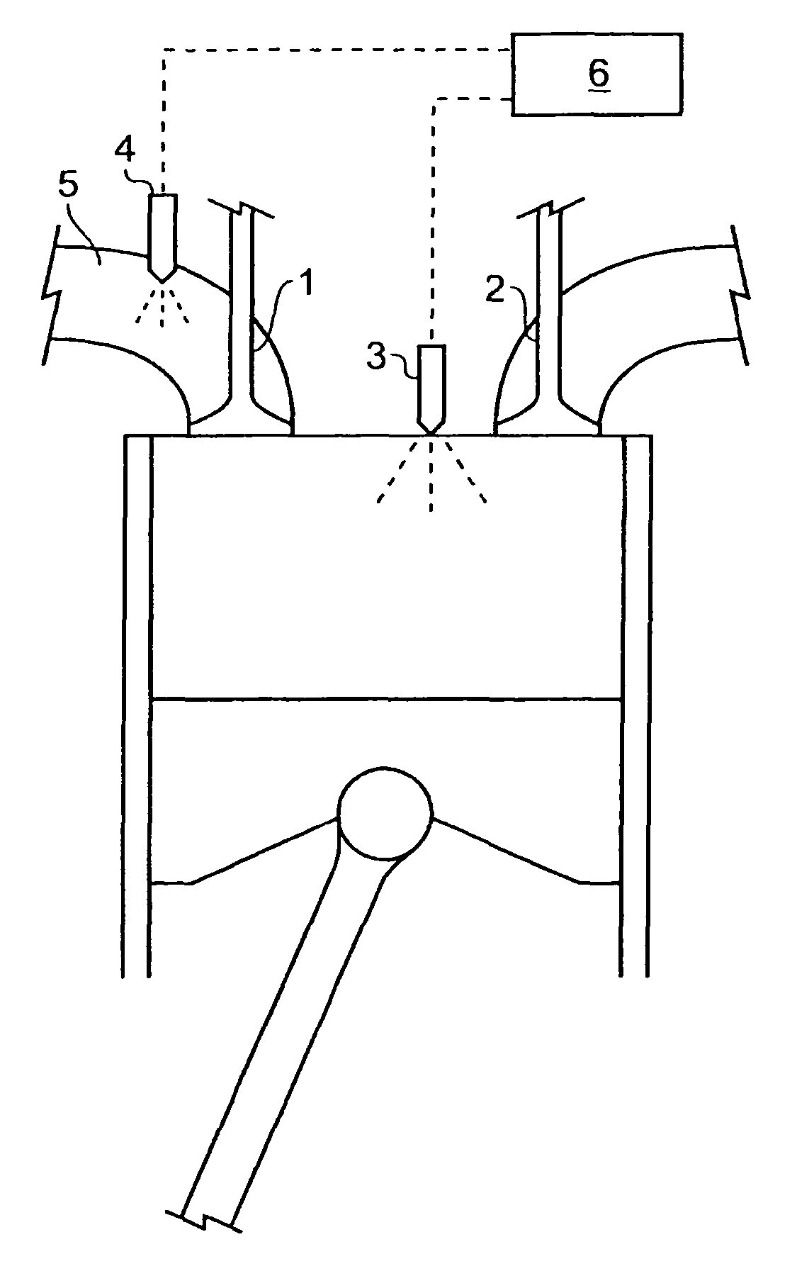
[0083]The invention is now described by reference to experiments conducted in relation to dual-fuelling of CI engines using a Ricardo E6, single cylinder, four stroke research engine shown schematically in FIG. 66. The engine is fitted with a head having two poppet valves 1, 2 with a direct diesel injector 3 that allows multi-split injection (up to 5 per cycle) and is fed by a common rail with a maximum pressure of 1600 bars. The rail pressure is independently controllable by the fuel pump. A supplementary injector 4 is also mounted on the air intake pipe 5 to allow the part injection of bioethanol. The two fuel injectors 3, 4 are controlled by a central unit 6, which varies the injection timings and fuel qualities. The engine is adapted to run between 500 rpm and 3000 rpm but tests were mostly conducted at a low speed of 1000 rpm where susceptibility to engine knock is greater, this being an issue with which the invention is concerned.

[0084]The engine is fi...


PUM


Abstract

A compression ignition engine is supplied with a first fuel in a flow of air and a second fuel is injected into the combustion chamber. The first fuel comprises a more volatile fuel than diesel such as ethanol, LPG or other combustible gas; the second fuel comprises diesel or biodiesel; and the second fuel is injected in multiple pulses in each ignition cycle with the first pulse acting as a pilot pulse to trigger ignition, and the timing of the second pulse being such as to modify the temperature through evaporation of the second fuel and thereby reduce the combustion temperature and mitigate knock susceptibility. Preferably the pilot pulse is followed by a single further pulse of the second fuel in the ignition cycle. The engine may be controlled to operate in two different modes, one mode for light and medium load conditions when there is only a pilot pulse injection of the second fuel which reduces NOx and soot emissions, and the other mode for higher load conditions when there is a pilot pulse injection followed by a main pulse injection of the second fuel. The first fuel may comprise bioethanol and or one or more of the following: ethanol, butanol, propanol, lpg, natural gas, hydrogen.

Description

[0001]The present application is a 35 U.S.C. §371 submission of international application number PCT / EP2009 / 052476, entitled Multi-Fuelling an Engine and filed 2 Mar. 2009, which was published in the English language on 3 Sep. 2009 with publication number WO 2009 / 106647 A1, and which claims the benefit of the filing date of GB 0803708.7, filed 28 Feb. 2008.TECHNICAL FIELD[0002]This invention relates to a method of operating a compression ignition engine using multi-fuelling.[0003]Dual-fuelling of engines is well known and has been investigated for numerous reasons including the improvement of engine emissions and to reduce dependence on fossil fuels such as gasoline and diesel. The interest in dual-fuelling continues with increased concerns of global warming and expectation of stricter engine emission regulations, and the promotion of bio fuels. Biofuels are considered to be more carbon neutral in that they are manufactured from a biomass that has absorbed carbon dioxide from the en...

Claims


Application Information

Patent Timeline
Patent Type & Authority Patents(United States)
IPC IPC(8): F02B7/00
CPCF02D19/0647F02D19/081F02D41/0025F02D41/402F02D19/061F02D19/0655F02D41/0027Y02T10/36Y02T10/44F02D19/084Y02T10/30Y02T10/40F02D19/10F02D41/3047F02D41/405
Inventor COURTOY, PIERRESMITH, ANDREW FRANCES GAMBLEGREENHALGH, DOUGLAS
Owner G VOLUTION
Why Eureka
Try Eureka