System and method for producing dry formulations

a technology of spray drying and formulation, which is applied in the direction of washing apparatus, lighting and heating apparatus, furnace types, etc., can solve the problems of too large losses to the vessel wall, excessive consumption of substance in the adjustment of the relatively complicated process, and extremely limited quantities of new synthesized materials

Active Publication Date: 2013-01-08
ZICCUM AB
View PDF21 Cites 10 Cited by
  • Summary
  • Abstract
  • Description
  • Claims
  • Application Information

AI Technical Summary

Benefits of technology

[0007]It is an object of the present invention to provide a spray drying system adapted to reliable performance of obtaining small amounts of powdered formulations with negligible losses.
[0009]It is a another object of the invention to provide a spray drying system which admits a suitably extended residence time at ambient temperature, thereby being able to process normally labile agents.
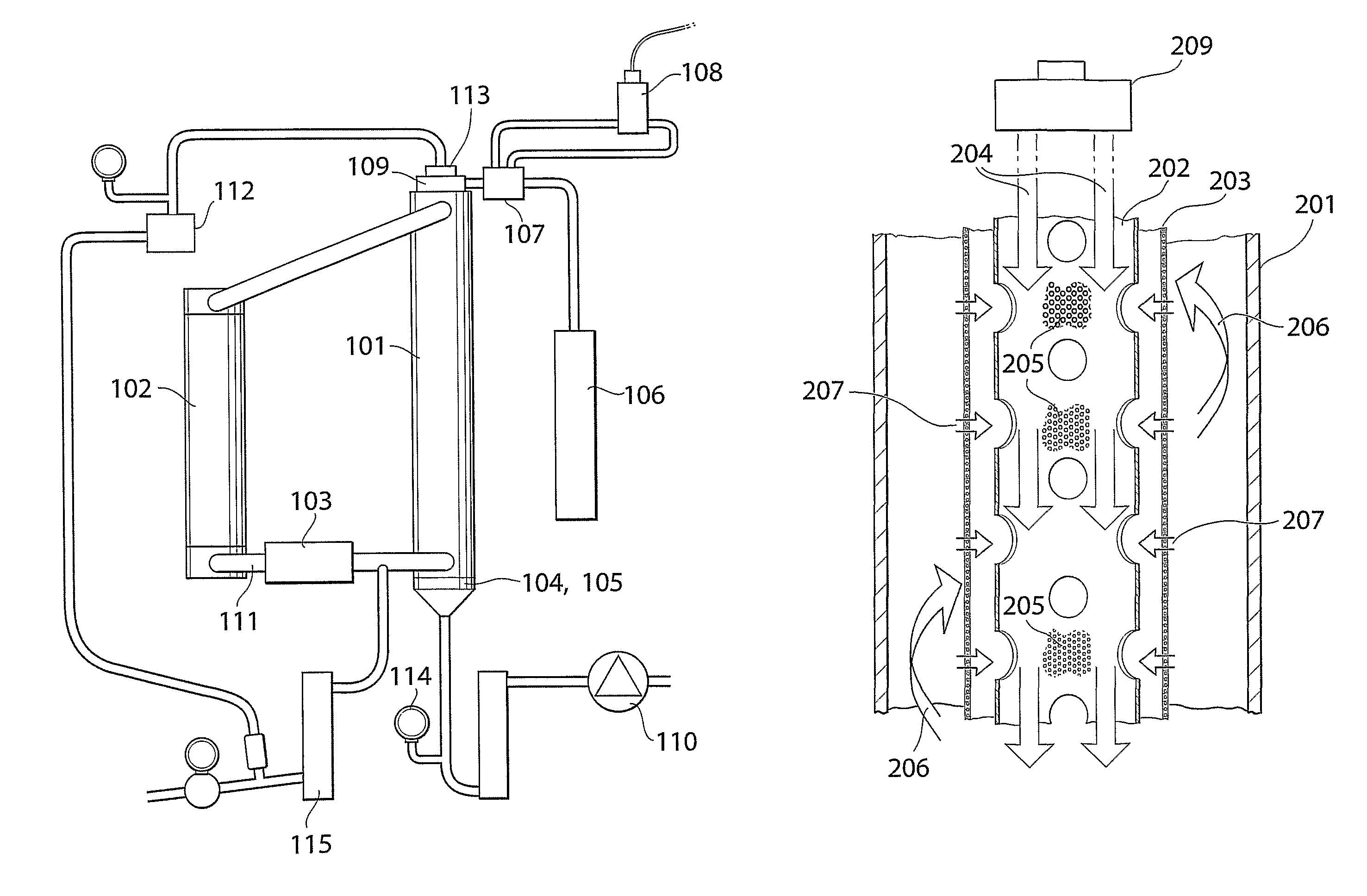
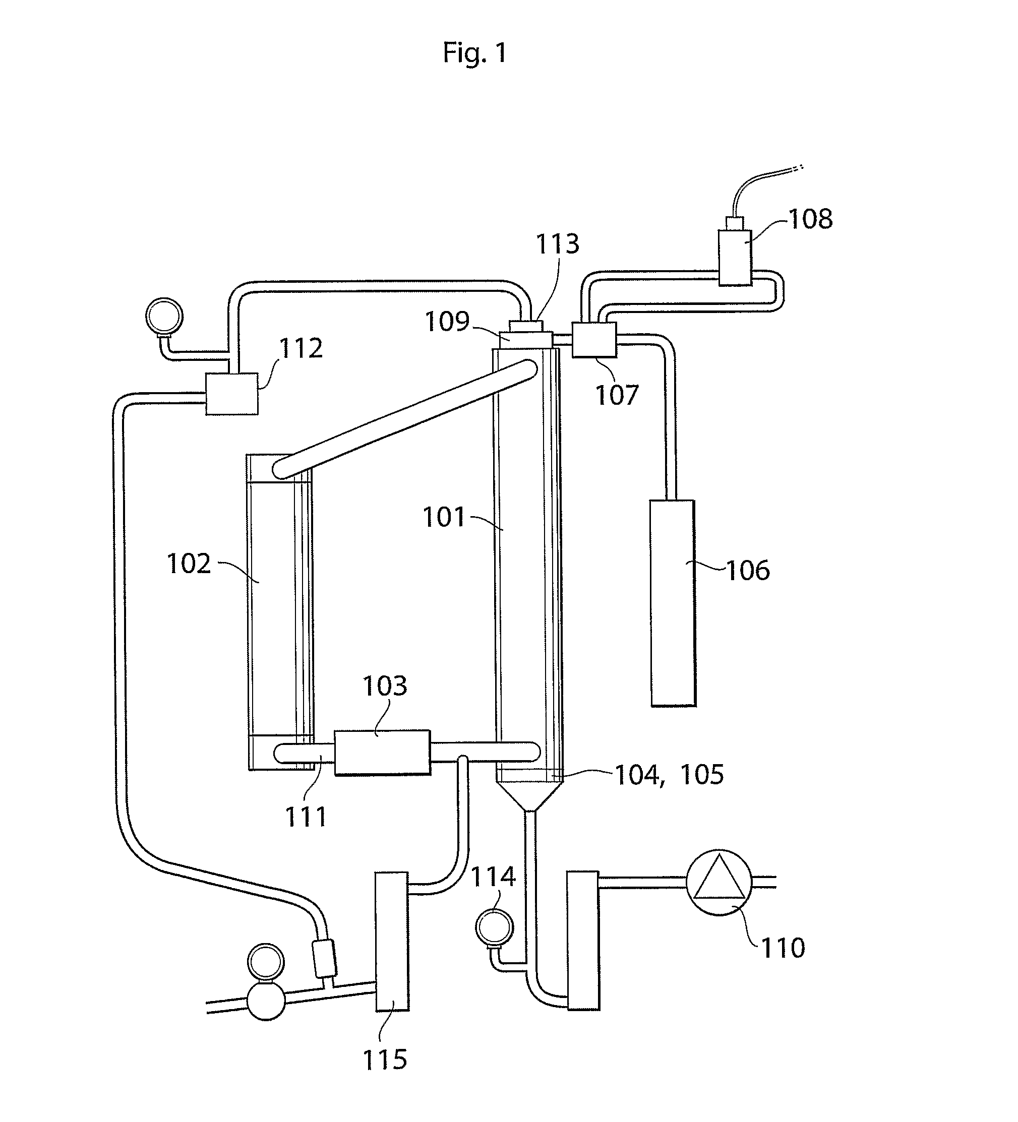
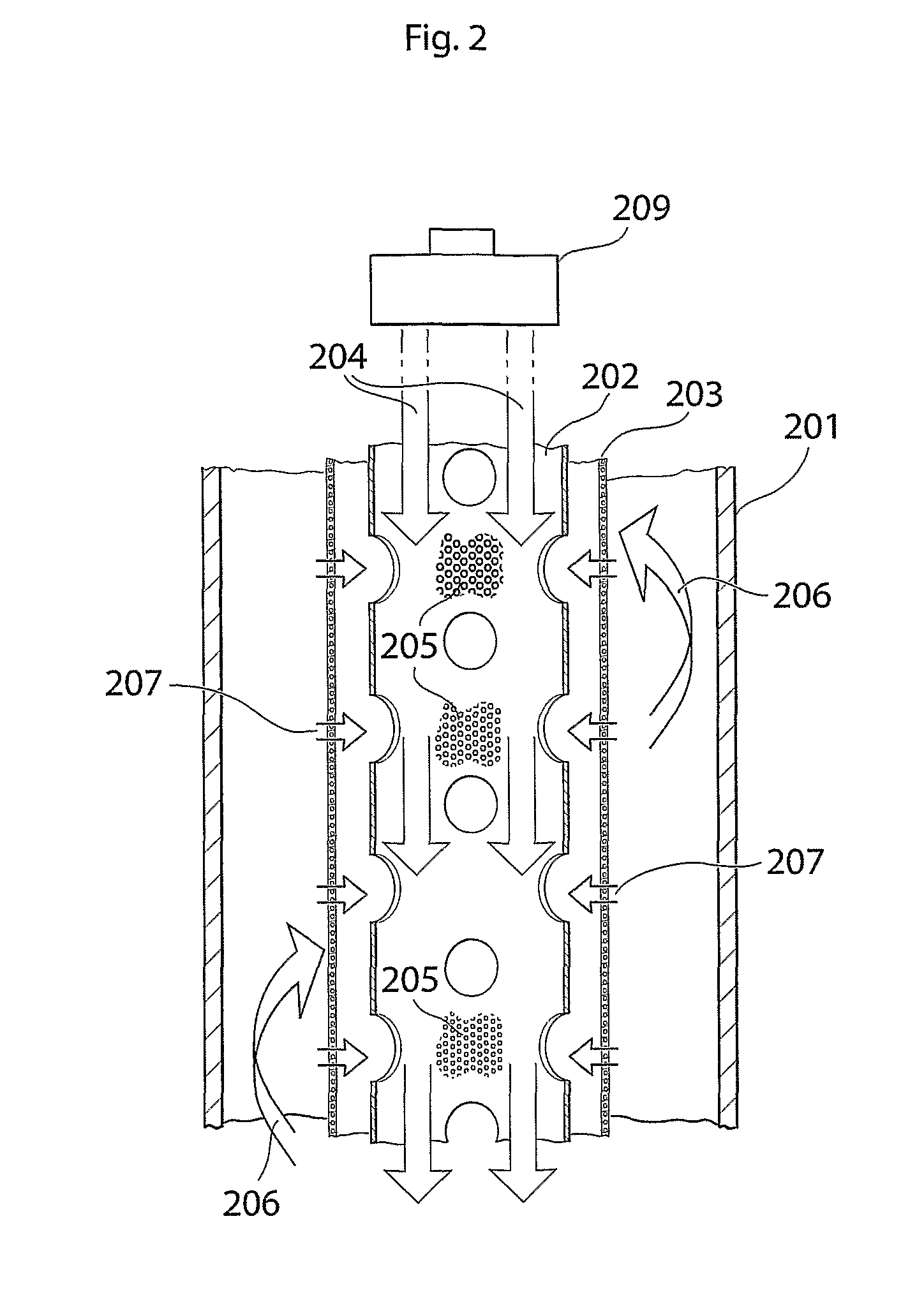
[0013]The tube reactor also comprises a reactor housing covering said process tube and membrane sleeve, preferably in a sealing manner. The housing is provided with features to introduce the necessary process fluids and to drive the reactor. An aerosol generating device is provided at the top of the reactor and is downwardly directed into the process tube with a liquid chamber for receiving an amount of solution with an agent to be processed to particles. i.e. having an opening located in its bottom part for dispensing aerosol droplets. Preferably the nebulizer is a mesh nebulizer not requiring any feeding gas (as opposed to jet nebulizers). It may also be preferable that vacuum is applied to the liquid chamber, especially if solutions with low surface tension are used or if liquid seep-through with large hanging droplets blocking aerosolization is anticipated. A vacuum of about 2-10 cmvp is normally sufficient to retract the liquid and permitting very short driving cycles. A dynamic vacuum with a pressurized air injector is a practically conceivable method. These arrangements advantageously increases the flexibility of solutions for aerosolization feasible to use with the invention which extends to lipid soluble substances, while permitting excellent control over the aerosolization process, which typically forms aerosol droplets in the size range of 4-20 μm. In this respect, the skilled person perceives that the droplets size depends on the physical and chemical characteristics of the solution.
[0017]In a special embodiment for reducing aerosol losses to the membrane wall, the ascending air flow is arranged to generate a radial influx of sheath air through the membrane. The influx rate of the radial sheath air, preferably is less than the diffusion rate of vapor through the membrane, i.e. the Peclet number at the membrane is substantially less than 1.
[0019]It is an important aspect of the presently invented system that it is arranged for reducing losses of aerosolized material to the membrane wall. For this purpose an electrostatic charge neutralizer, such as a Po-210-source, located in the vicinity of the nebulizer opening. Many other types of neutralizers are conceivable to persons skilled in the art. Also other means to reduce or eliminate material losses have previously been discussed and can be employed separately or in combination when realizing the present invention. The previously described inlet air arrangement to the process tube, the radial sheath air flow and the laminar condition in the inner section of the process tube contribute to increase the yield.

Problems solved by technology

It is easy to perceive that these newly synthesized materials may appear in both extremely limited quantities and in forms which are difficult to handle.
In milling procedures there are too large losses to the vessel walls and for supercritical spray drying the adjustment of the relatively complicated process tend to consume too much substance before a sufficient quality and quantity of the materials have been obtained.
However, the high volumetric flow rate through the apparatuses is unsuitable for production goals around 100 mg.
The draw backs of this system are the complicated method by which the absorptive pellets of the drying column regularly must be changed, and the fact that the absorptive material will be contaminated with the dried substances.
This countercurrent method cannot be used for pharmaceutical agents with a desired product particle size of <5 μm, where settling speeds are in the range of mm / min.

Method used


Image

  • System and method for producing dry formulations
  • System and method for producing dry formulations
  • System and method for producing dry formulations

Examples


Embodiment Construction

[0007]It is an object of the present invention to provide a spray drying system adapted to reliable performance of obtaining small amounts of powdered formulations with negligible losses.

[0008]It is also an object of the present invention to obtain a spray drying system which overcomes the limits of settling speed associated with conventional counter-current systems.

[0009]It is a another object of the invention to provide a spray drying system which admits a suitably extended residence time at ambient temperature, thereby being able to process normally labile agents.

[0010]These and other objects will be apparent from the following specification and its appended claims.

[0011]The present invention relates in general terms to a spray drying system adapted to provide a composition of dry, or essentially solvent free, particles from a solution of an agent. The process flows described with the system and the method generally are referred to “gas flows” or “air flows” and these terms have ...


PUM

PropertyMeasurementUnit
sizeaaaaaaaaaa
Peclet numberaaaaaaaaaa
particle sizeaaaaaaaaaa

Abstract

The invention relates to a spray drying system and a method for its operation that provides a composition of dry. or essentially solvent free, particles from a solution of an agent. The system comprises a generally vertical tube reactor arranged for counter-current removal of solvent from a process flow fed with aerosol droplets of solution descending from the top said reactor with an ascending gas flow. The reactor includes a perforated process tube for transportation of the process flow from the outlet of an aerosol generating device to a dry particle collecting device. A membrane sleeve essentially surrounds the peripheral area of said process tube and separates the descending process stream from the ascending gas stream. Vaporized solvent is transported from the process stream to the ascending gas stream. A reactor housing is sealingly covering said process tube and membrane sleeve and is provided with means for introducing and / or removing the process fluids.

Description

[0001]This application is a 371 of PCT / SE2008 / 051065 filed Sep. 24, 2008 and claims priority under 35 U.S.C. §119 of U.S. Application Ser. No. 60 / 974,501 filed Sep. 24, 2007.FIELD OF INVENTION[0002]The present invention relates to a spray drying system and methods of spray drying adapted for making small amounts of powder.BACKGROUND OF INVENTION[0003]In the early stage of drug development a vast number of new chemical compounds frequently are synthesized, often using pioneering chemistry at considerable effort and expense in order to supply various preclinical test programs with raw material. It is easy to perceive that these newly synthesized materials may appear in both extremely limited quantities and in forms which are difficult to handle. It is therefore a demand to bring such raw drug candidates into a manageable form more adapted to the models already developed for making the initial necessary steps to study their characteristics. A number of general requirements may already ...

Claims


Application Information

Patent Timeline
Patent Type & Authority Patents(United States)
IPC IPC(8): F26B3/00
CPCB01D1/18B01J2/04F26B3/12
Inventor GERDE, PER
Owner ZICCUM AB
Why Eureka
Try Eureka