Mesogenic stabilizers

a technology of stabilizers and stabilizers, applied in the field ofmesogenic stabilizers, can solve the problems of not being able to achieve the net linear polarization of transmitted radiation, not being well suited to use under certain low-light conditions, and being limited in their ability to store or display information

Active Publication Date: 2013-01-08
TRANSITIONS OPTICAL INC
View PDF107 Cites 60 Cited by
  • Summary
  • Abstract
  • Description
  • Claims
  • Application Information

AI Technical Summary

Problems solved by technology

As such, while conventional linearly polarizing elements are useful in reducing glare associated with reflected light, they are not, however, well suited for use under certain low-light conditions, because of the static coloring agent.
In addition, because conventional linearly polarizing elements have only a single, tinted linearly polarizing state, they are limited in their ability to store or display information.
Thus, while dichroic materials are capable of selectively absorbing one of two orthogonal plane polarized components of transmitted radiation, if the molecules of the dichroic material are not suitably positioned or aligned, no net linear polarization of transmitted radiation will be achieved.
Conventional photochromic elements, however, that do not include linearly polarizing filters are generally not adapted to linearly polarize radiation.
Therefore, conventional photochromic elements are not capable of reducing glare associated with reflected light to the same extent as conventional linearly polarizing elements.
This conformational change can result in a change in the amount of physical space that the compound occupies.
The presence of stabilizers in organic materials containing dichroic materials, such as photochromic-dichroic materials, can disrupt alignment of the dichroic materials, resulting in an undesirable reduction in absorption ratio values.
Alternatively or additionally, when the organic material is composed of or contains liquid crystal materials, such as liquid crystal polymers, the presence of stabilizers can undesirably disrupt alignment of the liquid crystal materials.
Still further alternatively or additionally, to disrupting liquid crystal alignment, the stabilizers may not be sufficiently soluble in the liquid crystal material, such as a liquid crystal polymer matrix, resulting in an undesirable reduction in clarity (e.g., an increase in haze) of the material.

Method used


Image

  • Mesogenic stabilizers
  • Mesogenic stabilizers
  • Mesogenic stabilizers

Examples


example 1

[0241]Step 1

[0242]To a reaction flask containing 2000 mL of N,N-dimethylacetamide was added methyl 4-hydroxy benzoate (609 g, 4 mol), 6-chloro-1-hexanol (656 g, 4.8 mol), sodium iodide hydrate (74.4 g, 0.4 mol), and sodium carbonate anhydrous (848 g, 8 mol). The resulting suspension was stirred and heated to about 115° C. for 8 hours. The solution was cooled to room temperature and filtered. The recovered solid was washed with 500 mL of N,N-dimethylacetamide. The filtrate was concentrated under reduced pressure and the resulting residue was poured into 10 L of distilled water under stirring. A white solid was obtained after filtration followed by rinsing with distilled water. The product was used for next step without further purification.

[0243]Step 2

[0244]To a reaction flask containing the product from Step 1 was added sodium hydroxide (192 g, 4.8 mol), water (768 mL), and ethanol (2000 mL). The resulting suspension was heated to reflux for 30 minutes. The solution was cooled to 65...

example 2

[0256]Step 1

[0257]The procedures of Steps 1 and 2 of Example 1 were followed except that 3-chloro-1-propanol and methyl 4-(3-hydroxypropoxy)benzoate were used in place of 6-chloro-1-hexanol in Step 1 and methyl 4-(6-hydroxyhexoxy)benzoate in Step 2. A white solid was recovered as the product. Nuclear Magnetic Resonance (NMR) showed that the product had a structure consistent with 4-(3-hydroxypropoxy)benzoic acid.

[0258]Step 2

[0259]To a reaction flask containing 100 mL of chloroform was added the product from Step 1 (9.81 g, 50.0 mmol), acrylic acid (31.5 g, 437.6 mmol), hydroquinone (2.0 g, 18.2 mmol) and p-toluenesulfonic acid (2.0 g, 10.5 mmol). The resulting mixture was refluxed for 6 hours using a Dean-Stark apparatus. The resulting solution was allowed to cool down to room temperature and diluted with a 3 to 4-fold excess of ether, washed with warm water (50° C.) (100 mL×2) and dried over anhydrous magnesium sulfate. After evaporation of the solvent, the recovered product was re...

example 3

[0273]Step 1

[0274]The procedures of Steps 1 to 8 of Example 2 were followed except that 6-chlorohexan-1-ol and 8-chlorooctan-1-ol were used in place of 3-chloro-1-propanol in Step 1 and 6-chlorohexan-1-ol in Step 3, respectively. A white solid was recovered as the product (3.4 g). Nuclear Magnetic Resonance (NMR) showed that the product had a structure consistent with 4-((4-((8-(4-((4-((4-((6-(acryloyloxy)hexyl)oxy)benzoyl)oxy)phenoxy)carbonyl)phenoxy)octyl)oxy)-4-oxobutanoyl)oxy)-1,2,2,6,6-pentamethylpiperidine as represented by the following graphic formula.

[0275]


PUM

PropertyMeasurementUnit
temperatureaaaaaaaaaa
speedaaaaaaaaaa

Abstract

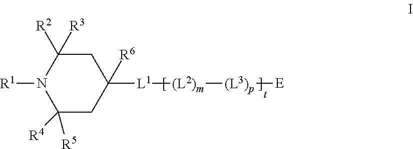
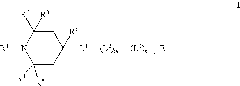
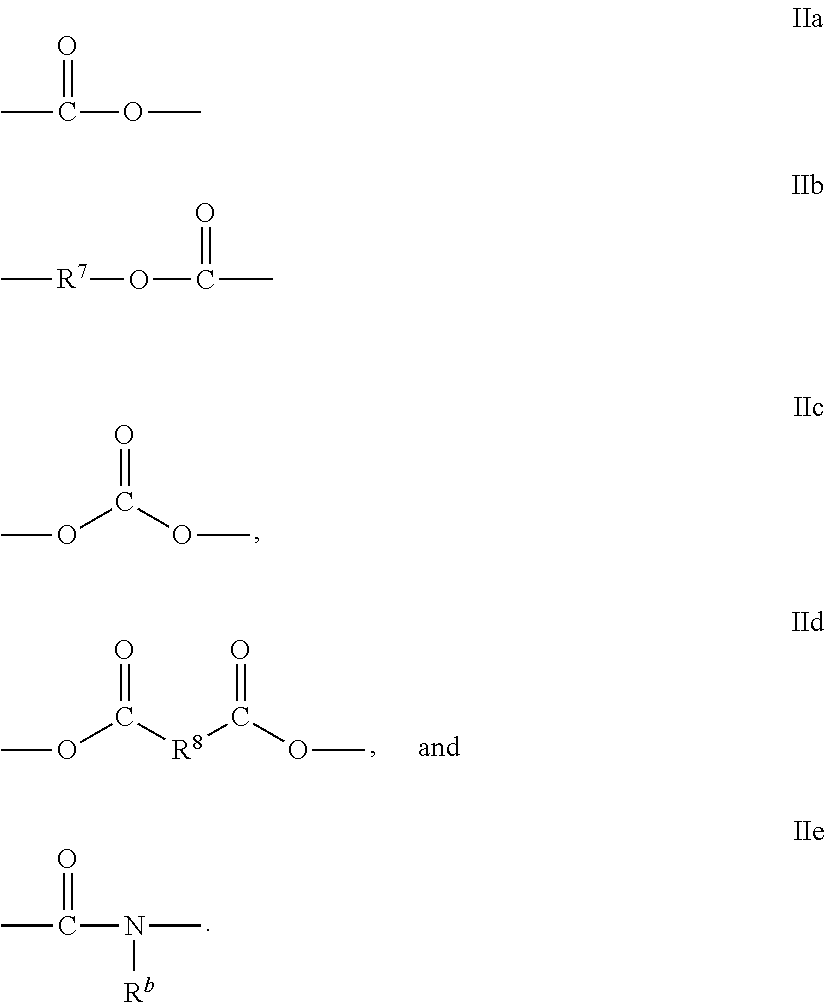
The present invention relates to compounds represented by the following Formula I,in which R1-R6 can each independently be selected from hydrogen or hydrocarbyl (e.g., methyl); L1 is a divalent linking group, such as a bond or —OC(O)—R8—C(O)O—, where R8 can be divalent hydrocarbyl (e.g., —CH2CH2—); each L2 independently represents a flexible segment, such as divalent linear or branched C1-C25 alkyl; each L3 independently represents a rigid segment including, for example, optionally substituted phenylen-1,4-diyl groups; t is from 1 to 4; m and p are each independently from 0 to 4 for each t, provided that the sum of m and p is at least 1 for each t; and E can be hydrogen or hydrocarbyl. The present invention also relates to compositions, such as liquid crystal compositions, and articles, such as optical elements, that include the compound represented by Formula I.

Description

CROSS REFERENCE TO RELATED APPLICATIONS[0001]This application is entitled to and claims priority to the following United States Patent Applications as a continuation-in-part under 35 U.S.C. §120: U.S. patent application Ser. No. 13 / 051,130, filed on Mar. 18, 2011; U.S. patent application Ser. No. 12 / 489,811, filed Jun. 23, 2009; U.S. patent application Ser. No. 12 / 489,843, filed Jun. 23, 2009; U.S. patent application Ser. No. 12 / 163,116, filed Jun. 27, 2008; and U.S. patent application Ser. No. 12 / 163,180, filed Jun. 27, 2008, each of which is incorporated herein by reference in its entirety.FIELD OF THE INVENTION[0002]The present invention relates to compounds having one or more stabilizer groups, such as hindered amine light stabilizer groups, and one or more mesogen groups or segments, and to compositions, such as liquid crystal compositions, and articles of manufacture, such as optical elements, containing such compounds.BACKGROUND OF THE INVENTION[0003]The molecules of a liquid...

Claims


Application Information

Patent Timeline
Patent Type & Authority Patents(United States)
IPC IPC(8): C09K19/52C07D211/00C09K19/00C09K19/06C07C69/76
CPCC07D401/12C07D211/48C09K19/3483C09K19/60C09K19/54Y10T428/10C09K2019/0448Y10T428/1036C09K2323/00C09K2323/03
Inventor XU, RUISONGDAI, XIAO-MANKUMAR, ANILHE, MENGLI, CHENGUANGYOEST, RACHAEL L.
Owner TRANSITIONS OPTICAL INC
Why Eureka
Try Eureka