
Short wave infrared multi-conjugate liquid crystal tunable filter

a infrared multi-conjugate technology, applied in the field of short wave infrared multi-conjugate liquid crystal tunable filter, can solve the problems of transmission loss, inability to pass desired light energy, transmission loss, etc., and achieve excellent out-of-band rejection ratio, high transmission, and fast tuning speed

Active Publication Date: 2013-03-19
CHEMIMAGE TECH LLC
View PDF49 Cites 6 Cited by
  • Summary
  • Abstract
  • Description
  • Claims
  • Application Information

AI Technical Summary

Benefits of technology

The present invention provides a filter that can transmit information while filtering out unwanted signals. This results in better signal quality and a higher level of protection against interference. The filter also has the advantage of being able to change quickly and accurately.

Problems solved by technology

Multiple stages of birefringence and / or polarization filtering can be disposed serially to obtain better wavelength discrimination, but there are complications.
For example, if the stages have bandpasses that are not well aligned, particularly if subject to tuning, then desired light energy may be blocked rather than passed.
Each successive filter stage is likely to cause some transmission loss.
Each polarizer typically has an inherent transmission loss, even with respect to light energy that is plane polarized and aligned to the polarizer.
If a large number of stages are needed to provide a high degree of discrimination or a very narrow bandpass, the level of light energy passing the filter may be low.
A low transmission ratio may require that light energy be collected for a relatively long time to obtain an image or a measurement.
In order to achieve such resolution, dimensional precision is necessary, which makes the filters expensive.
This has the disadvantage of reducing the proportion of light that is transmitted versus the proportion that is rejected.

Method used


Image

  • Short wave infrared multi-conjugate liquid crystal tunable filter
  • Short wave infrared multi-conjugate liquid crystal tunable filter
  • Short wave infrared multi-conjugate liquid crystal tunable filter

Examples


Embodiment Construction

[0049]Reference will now be made in detail to the preferred embodiments of the present disclosure, examples of which are illustrated in the accompanying drawings. Wherever possible, the same reference numbers will be used throughout the drawings to refer to the same or like parts.

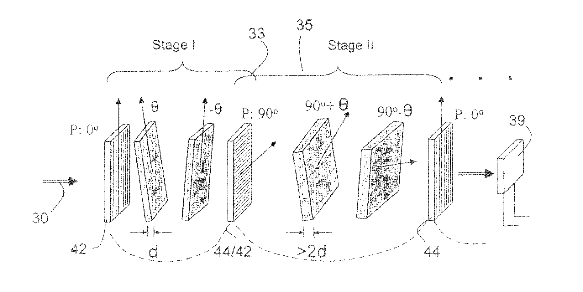
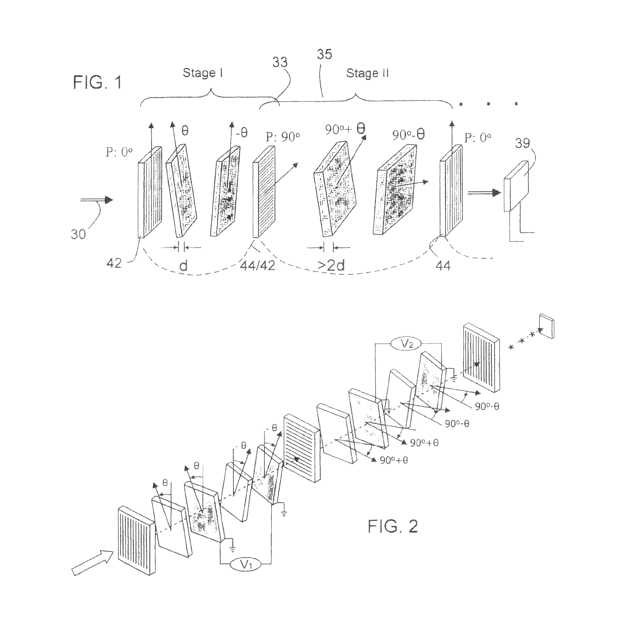
[0050]The invention concerns optical filters having tunable wavelength pass bands, for use in hyperspectral imaging. Inventive filter configurations are provided with conjugated stages having distinct attributes. Stages with narrow periodic wavelength passbands are serially arranged with stages having large free spectral range.

[0051]The filter stages comprise serially placed birefringent retarders and polarizers. The retarders have thickness and rotational relationships designed to pass selected wavelengths. The retarders can use one or more liquid crystal tunable elements for all or a tunable part of their total retardation.

[0052]In the context of the present invention, birefringent stacked filters are app...


PUM

PropertyMeasurementUnit
thicknessaaaaaaaaaa
FWHMaaaaaaaaaa
rotation anglesaaaaaaaaaa

Abstract

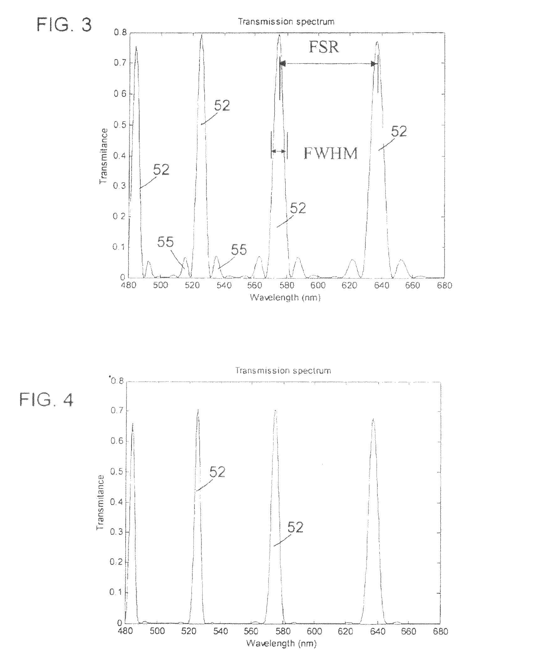
A SWIR hyperspectral imaging filter has serial stages along an optical signal path with angularly distributed birefringent retarders and polarizers. The retarders can include active retarders such as tunable liquid crystal birefringent elements, passive retarders such as fixed retarders, and / or combinations thereof. Distinctly different periodic transmission spectra are provided by different filter stages, each having multiple retarders, in particular with some stages having broad bandpass peaks at wide spectral spacing and other stages have very narrow closely spaced peaks. The respective spectra include at least one tunably selectable band at which the transmission spectra of the filter stages coincide, whereby the salutary narrow bandpass and wide spectral spacing ranges of different stages apply together, resulting in a high finesse wavelength filter suitable for spectral imaging. The filter may be configured to provide faster switching speed and increased angle of acceptance and may operate in the rage of approximately 850-1700 nm.

Description

RELATED APPLICATIONS[0001]The present application claims priority under 35 U.S.C. §119(e) to the following U.S. provisional patent applications, hereby incorporated by reference in their entireties: No. 61 / 324,963, filed on Apr. 16, 2010, entitled “Short-Wavelength Infrared (SWIR) Multi-Conjugate Liquid Crystal Tunable Filter”; and No. 61 / 403,141, filed on Sep. 10, 2010, entitled “Systems and Methods for Improving Imaging Technology.”BACKGROUND[0002]Optical bandpass filters that rely on birefringence are known in a number of different configurations. Birefringence is a characteristic of certain crystals wherein there is a difference in optical index for orthogonal light components that are aligned to the respective fast and slow axes of the crystal. If a plane polarized input light signal is aligned at 45° to the fast and slow axes a birefringent crystal, for example, the crystal induces a differential phase retardation between a component that is parallel to the slow axis versus th...

Claims


Application Information

Patent Timeline
Patent Type & Authority Patents(United States)
IPC IPC(8): G02F1/1335G02F1/03G02F1/07
CPCG02B5/208G02B5/3083G02F1/13471G02F1/13363G02F1/13473G02F2001/133633G02F1/133633
Inventor VOIGT, THOMASSHI, LEILI, ZILIVENTOURIS, GEORGEFUHRMAN, MICHAEL
Owner CHEMIMAGE TECH LLC
Learn More