Receiver dynamic power management

a power management and receiver technology, applied in the direction of gain control, transmission monitoring, helmet covers, etc., can solve the problems of increasing the cost of power consumption, and achieve the effects of reducing noise floor, high performance mode, and reducing ip3

Active Publication Date: 2013-04-23
MARVELL ASIA PTE LTD
View PDF31 Cites 32 Cited by
  • Summary
  • Abstract
  • Description
  • Claims
  • Application Information

AI Technical Summary

Benefits of technology

[0006]In one embodiment, a level of amplification of an early-stage AGC is monitored to determine if the received signal is weak or strong. The RSSI is used to determine if the signal-of-interest at the antenna is weak or strong. Using AGC level and RSSI as two state inputs, a decision block can be used to set a number of operating modes. First, when the signal at the antenna is strong and the signal-of-interest at the antenna is weak, a high performance mode may be used to both lower the noise floor and diminish IP3, at the cost of increased power consumption. Second, when the signal at the antenna is strong and the signal-of-interest at the antenna is also strong, a power-save mode can be implemented to reduce signal processing and increase battery life. Third, when the signal at the antenna is weak and the signal-of-interest at the antenna is also weak, a low-noise mode may be used to lower the noise floor but allow a certain degree of IP3, to reduce some of the signal processing overhead and save energy over the high performance mode.

Problems solved by technology

First, when the signal at the antenna is strong and the signal-of-interest at the antenna is weak, a high performance mode may be used to both lower the noise floor and diminish IP3, at the cost of increased power consumption.

Method used


Image

  • Receiver dynamic power management
  • Receiver dynamic power management
  • Receiver dynamic power management

Examples


Embodiment Construction

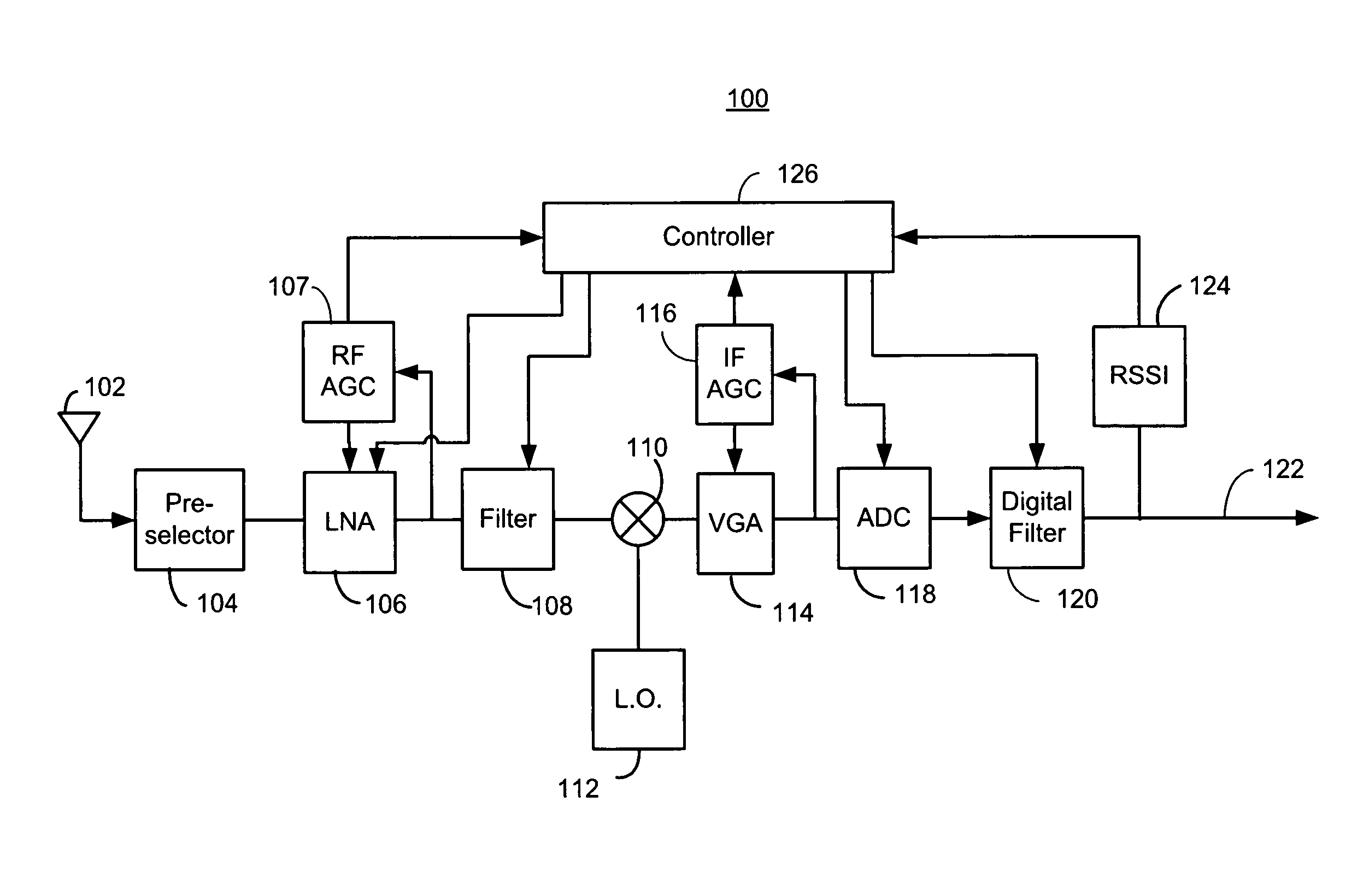
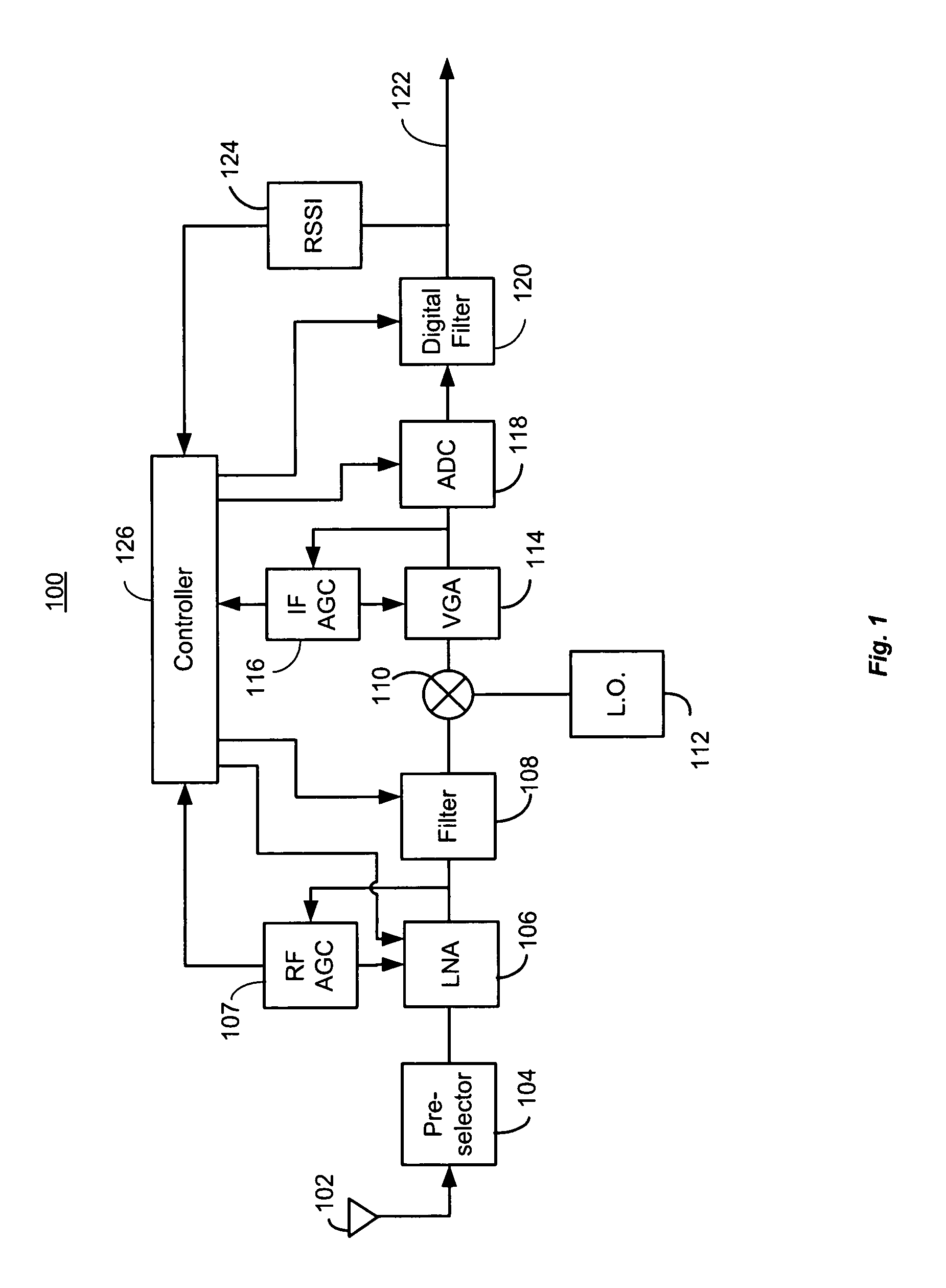
[0014]FIG. 1 is a block diagram of a receiver 100 arranged for dynamic power management. The receiver 100 may include an antenna 102, a preselector 104, a low noise amplifier (LNA) 106 with variable gain under the control of a radio frequency (RF) automatic gain control 107 (AGC). An adaptive filter 108 may be coupled to the LNA 106. The exemplary receiver 100 may also include a mixer 110, a local oscillator 112, a variable gain amplifier 114 controlled by a intermediate frequency automatic gain converter (IF AGC) 116, an analog-to-digital converter 118, a digital filter 120, and an output 122. The output 122 may be coupled to a received signal strength indicator (RSSI) generator 124. In some embodiments an antenna may not be required, for example, in a cable television set-top box. The preselector 104 may be a bandpass filter, often passive, used to remove received signals outside of a band range of interest. The AGC 107, may adjust internal gain stages of the LNA 106, to selective...


PUM


Abstract

A controller in a receiver monitors RSSI and AGC gain levels to determine signal conditions and adjust filter performance accordingly to optimize power consumption while providing acceptable signal quality. When RSSI level is high and AGC gain is low, a strong signal-of-interest is present. In this case, adaptive filter bias currents may be reduced raise the noise floor and degrade intermodulation to reduce power consumption because the strong signal-of-interest can tolerate the higher noise and distortion. When the RSSI level is low and AGC gain is high, a weak signal is present a low noise mode may be effected by increasing bias current to filters used to lower the noise floor, but intermodulation effects may still be tolerated so those filters may be cut back. Other cases are supported. RSSI and AGC gain level thresholds may be dynamically altered based on relative RSSI and AGC levels.

Description

CROSS-REFERENCE TO RELATED APPLICATION[0001]This application claims the benefit of U.S. Provisional Application No. 60 / 952,756, entitled “DYNAMIC POWER MANAGEMENT FOR A FM RECEIVER,” filed on Jul. 30, 2007, which is hereby incorporated by reference herein.DESCRIPTION OF RELATED ART[0002]Automatic gain control (AGC) is used in receivers and other circuits to automatically adjust signal levels. AGC circuits measure the output of a gain stage and increase or decrease a gain level to adjust the output to meet a criteria. For example, the gain level is adjusted to keep a peak level of an input signal just below a saturation level of a linear range of an amplifier lineup or signal conversion process. Typically, gain stage output measurements include all in-band signals, including not only a signal-of-interest but also noise and interferers.[0003]Another measurement made in many receivers is a receive signal strength indicator (RSSI). A well-known RSSI measurement is reflected by the numbe...

Claims


Application Information

Patent Timeline
Patent Type & Authority Patents(United States)
IPC IPC(8): H04B1/06H04B7/00
CPCA42B3/225A42B3/24H03G3/20
Inventor COUSINARD, DAVIDCLEMENT, PATRICKTU, CAO-THONG
Owner MARVELL ASIA PTE LTD
Why Eureka
Try Eureka