
Anti-reflection film having an antistatic hard coat and low refractive index layers and manufacturing method thereof

a technology of anti-reflection film and hard coat, which is applied in the field of anti-reflection film, can solve the problems of low productivity, reduced display quality, and hard coat layer made by curing acrylic materials, and achieves sufficient anti-static effect, reduce material costs, and reduce total usage of conductive particles

Active Publication Date: 2013-05-21
TOPPAN PRINTING CO LTD
View PDF14 Cites 25 Cited by
  • Summary
  • Abstract
  • Description
  • Claims
  • Application Information

AI Technical Summary

Benefits of technology

[0020]The present invention provides an anti-reflection film having an antistatic hard coat layer, in which conductive materials are added to a hard coat layer, and low refractive index layer on at least one surface of the transparent substrate, and further, having not only sufficient anti-reflection properties and antistatic properties but also excellent optical properties.
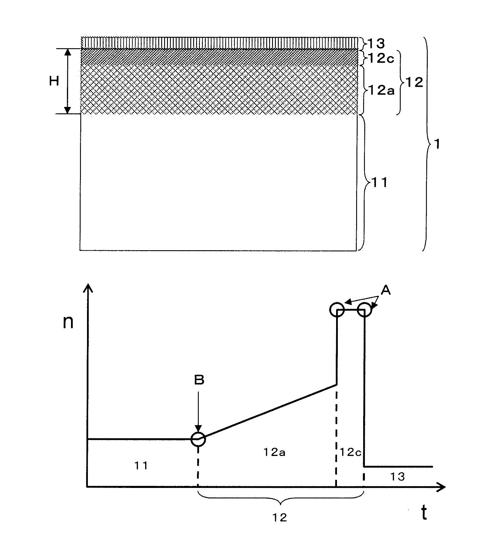
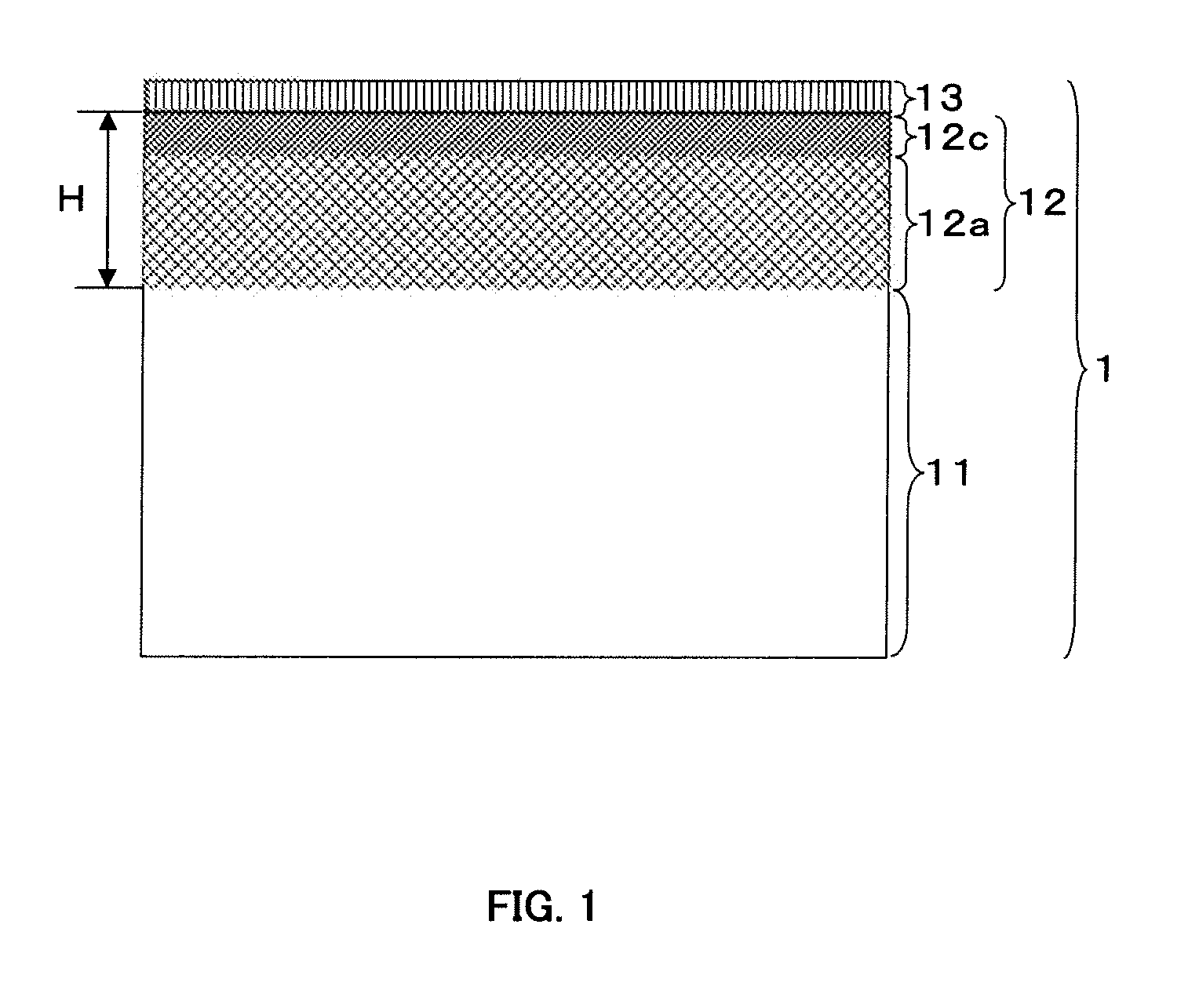
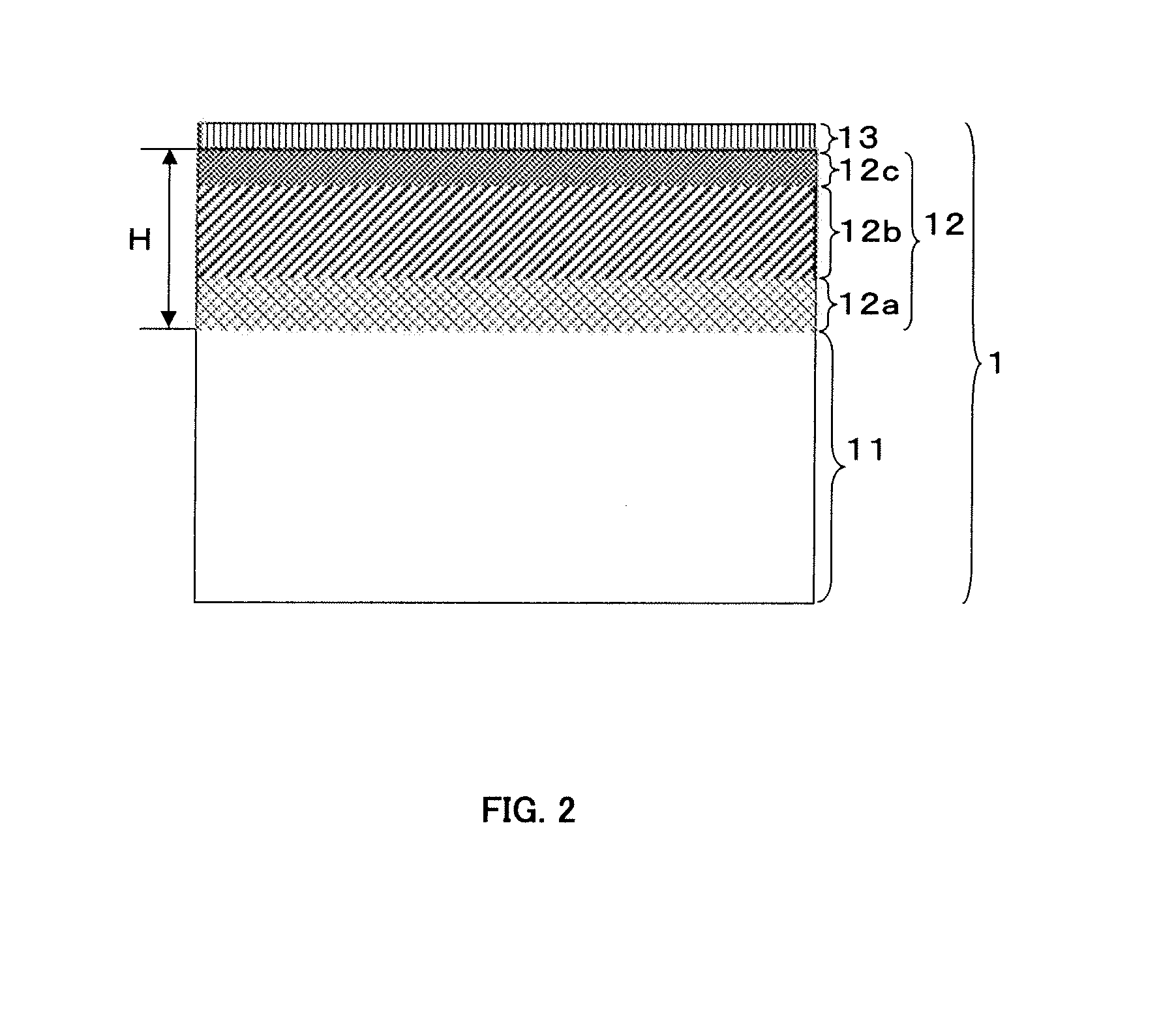
[0043]An anti-reflection film of the present invention has an antistatic hard coat layer and a low refractive index layer on at least one surface of the transparent substrate, the antistatic hard coat layer containing conductive particles and a binder matrix, the antistatic hard coat layer having a mixed layer, in which the transparent substrate and the binder matrix are mixed together with a gradient composition, and a localized layer, which includes the binder matrix and the conductive particles, the mixed layer being optically indistinguishable, the localized layer being optically distinguishable, and a thickness of the localized layer being in the range of 50-400 nm. Since a formation of the localized layer, in which conductive particles are concentrated, makes it possible to reduce total usage of the conductive particles and yet maintain sufficient antistatic effect, it is possible to reduce material costs and prevent a surface hardness and a visible light transmittance decrease of the anti-reflection film caused by an addition of excessive conductive particles. In addition, the production costs can be lower than those in the case where the antistatic layer is formed separately from the hard coat layer.
[0044]Moreover, the mixed layer in the anti-reflection film of the present invention is optically indistinguishable. As the composition (a ratio of the transparent substrate component and the binder matrix) in the mixed layer varies with gradient, there are no points at which an acute change in refractive index exists so that the interference generation caused by a difference in refractive index between the both layers adjacent to the mixed layer (the transparent substrate and the localized layer) at their boundary is prevented.
[0045]In addition, it is possible to make the localized layer work as a high refractive index layer to provide the anti-reflection film with an anti-reflection function, and is it possible to prevent the anti-reflection film from obtaining color unevenness by using an optically distinguishable layer having an optical thickness in the range of 50-400 nm as the localized layer in the anti-reflection film of the present invention. Moreover, it is also possible to ensure a hard coat function and prevent interference fringe generation by arranging the optically indistinguishable intermediate layer between the mixed layer and the localized layer. The localized layer can be a still better high refractive index layer if the refractive index thereof is larger than the refractive index of the intermediate layer and the difference in refractive index is in the 0.01-0.05 range. It is possible to make the anti-reflection film of the present invention have a high level of optical properties by an optical interference between the localized layer in the antistatic hard coat layer and the low refractive index layer which is arranged adjacent to the localized layer.

Problems solved by technology

The external light incident to a display surface is reflected on the surface so that a displayed image is interfered with by the reflected image and the quality of display decreases.
In the case where the anti-reflection layer is formed by a dry coating, while there is an advantage of fine thickness controllability, there is also a problem of low productivity due to a limitation of a deposition process performed in a vacuum chamber, which is unsuitable for mass production.
The hard coat layer made by curing an acrylic material, however, is liable to take charge because of its insulation quality and has a problem of attracting dust to the surface of the anti-reflection film in which the hard coat layer is arranged.
In the case where conductive materials are added to the anti-reflection film, a problem of an insufficient contrast occurs due to a fall in luminance during display of a white image (this luminance is referred to as white luminance) when the film is arranged on an LCD surface.
In the case of a method in which an antistatic function is provided by newly arranging an antistatic layer, the production cost becomes high due to an increase in the number of layers resulting in a fall in productivity.
In addition, since it is necessary in general to arrange an antistatic layer with high refractive index between the layers, color generation or color unevenness tends to occur by the antistatic layer.
Especially in the case where the antistatic layer and the low refractive index layer (the anti-reflection layer) are formed by a wet coating method, there was a problem of color unevenness of the anti-reflection film according to the unevenness in layer thickness.
However, the former type of anti-reflection film requires a large amount of conductive material and leads to problems such as increase in cost of material, decrease in hardness of the hard coat layer, decrease in visible light transmittance, and interference fringe generation caused by the difference in refractive index between the substrate and the hard coat layer etc.

Method used


Image

  • Anti-reflection film having an antistatic hard coat and low refractive index layers and manufacturing method thereof
  • Anti-reflection film having an antistatic hard coat and low refractive index layers and manufacturing method thereof
  • Anti-reflection film having an antistatic hard coat and low refractive index layers and manufacturing method thereof

Examples


example 1

Transparent Substrate

[0169]An 80 μm thick triacetyl cellulose film was prepared as the transparent substrate.

[0170]4.0 parts by weight of a dispersion liquid of antimony-doped tin oxide particles (ATO, average particle diameter: 8 nm, solid content ratio: 30 wt %, dispersion solvent: isopropyl alcohol) as the conductive particles, 7.8 parts by weight of dipentaerythritol hexaacrylate (DPHA), 7.8 parts by weight of pentaerythritol tetraacrylate (PETA) and 23.3 parts by weight of urethane acrylate UA-306T (made by Kyoeisha chemical Co., Ltd.) as the ionizing radiation curable material, 2.0 parts by weight of Irgacure 184 (by Ciba Japan) as the photopolymerization initiator, and 57.2 parts by weight of a solvent mixture of methyl ethyl ketone, dimethyl carbonate and diacetone alcohol having a blend ratio of 4:4:2 as the solvent were blended together to prepare a coating liquid for forming an antistatic hard coat layer with a solid content ratio of 40 wt % by weight.

[0171]The resultant ...

example 2

Transparent Substrate

[0174]An 80 μm thick triacetyl cellulose film was prepared as the transparent substrates.

[0175]1.7 parts by weight of a dispersion liquid of antimony-doped tin oxide particles (ATO, average particle diameter: 8 nm, solid content ratio: 30 wt %, dispersion solvent: isopropyl alcohol) as the conductive particles, 4.9 parts by weight of dipentaerythritol hexaacrylate (DPHA), 4.9 parts by weight of pentaerythritol tetraacrylate (PETA) and 14.7 parts by weight of urethane acrylate UA-306T (made by Kyoeisha chemical Co., Ltd.) as the ionizing radiation curable material, 1.5 parts by weight of Irgacure 184 (by Ciba Japan) as the photopolymerization initiator, and 73.8 parts by weight of a solvent mixture of methyl ethyl ketone, dimethyl carbonate and diacetone alcohol having a blend ratio of 4:4:2 as the solvent were blended together to prepare a coating liquid for forming an antistatic hard coat layer with a solid content ratio of 25 wt % by weight.

[0176]The resultant...

example 3

Transparent Substrate

[0179]An 80 μm thick triacetyl cellulose film was prepared as the transparent substrate.

[0180]4.0 parts by weight of a dispersion liquid of antimony-doped tin oxide particles (ATO, average particle diameter: 20 nm, solid content ratio: 30 wt %, dispersion solvent: isopropyl alcohol) as the conductive particles, 7.8 parts by weight of dipentaerythritol hexaacrylate (DPHA), 7.8 parts by weight of pentaerythritol tetraacrylate (PETA) and 23.3 parts by weight of urethane acrylate UA-306T (made by Kyoeisha chemical Co., Ltd.) as the ionizing radiation curable material, 2.0 parts by weight of Irgacure 184 (by Ciba Japan) as the photopolymerization initiator, and 57.2 parts by weight of a solvent mixture of methyl ethyl ketone, dimethyl carbonate and diacetone alcohol having a blend ratio of 4:4:2 as the solvent were blended together to prepare a coating liquid for forming an antistatic hard coat layer with a solid content ratio of 40 wt % by weight.

[0181]The resultant...


PUM

PropertyMeasurementUnit
optical thicknessaaaaaaaaaa
thicknessaaaaaaaaaa

Abstract

An anti-reflection film which has not only sufficient anti-reflection properties and antistatic properties but also excellent optical properties is provided. The anti-reflection film includes an antistatic hard coat layer and a low refractive index layer on a transparent substrate, the antistatic hard coat layer containing conductive particles and a binder matrix, the antistatic hard coat layer including a mixed layer in which the transparent substrate component and the binder matrix blend together with a gradient and a localized layer, the mixed layer being optically indistinguishable and the localized layer being optically distinguishable, and the localized layer having an optical thickness of 50-400 nm.

Description

CROSS REFERENCE TO RELATED APPLICATION[0001]This application is based on and claims the benefit of priority from the Japanese Patent Application number 2009-033719, filed on Feb. 17, 2009, the entire contents of which are incorporated herein by reference.BACKGROUND OF THE INVENTION[0002]1. Field of the Invention[0003]The present invention relates to an anti-reflection film which is arranged in order to prevent external light from reflecting on a window or a surface of display devices etc. Specifically, the present invention relates to an anti-reflection film applied on a surface of a liquid crystal display (LCD), CRT display, organic electroluminescent display (ELD), plasma display (PDP), surface-conduction electron-emitter display (SED) and field emission display (FED) etc. Among these, this invention relates to an anti-reflection film applied on a surface of an LCD, especially a transmission type LCD.[0004]2. Description of the Related Art[0005]In general, displays are used under ...

Claims


Application Information

Patent Timeline
Patent Type & Authority Patents(United States)
IPC IPC(8): G02B1/10B32B7/02G02B1/11G02B1/111G02B1/14G02B1/16G02B5/30G02F1/1335
CPCG02B1/11G02B1/118G02B1/12Y10T428/265Y10T428/24975G02B1/116G02B1/16
Inventor YOSHIHARA, TOSHIAKI
Owner TOPPAN PRINTING CO LTD
Learn More