Heat conduction-type barometric sensor utilizing thermal excitation
a barometric sensor and heat conduction technology, applied in the direction of instruments, heat measurement, fluid pressure measurement by thermal means, etc., can solve the problem of substantial nullness of sensitivity, and achieve the effect of simple structure, wide bandwidth and high precision
- Summary
- Abstract
- Description
- Claims
- Application Information
AI Technical Summary
Benefits of technology
Problems solved by technology
Method used
Image
Examples
first embodiment
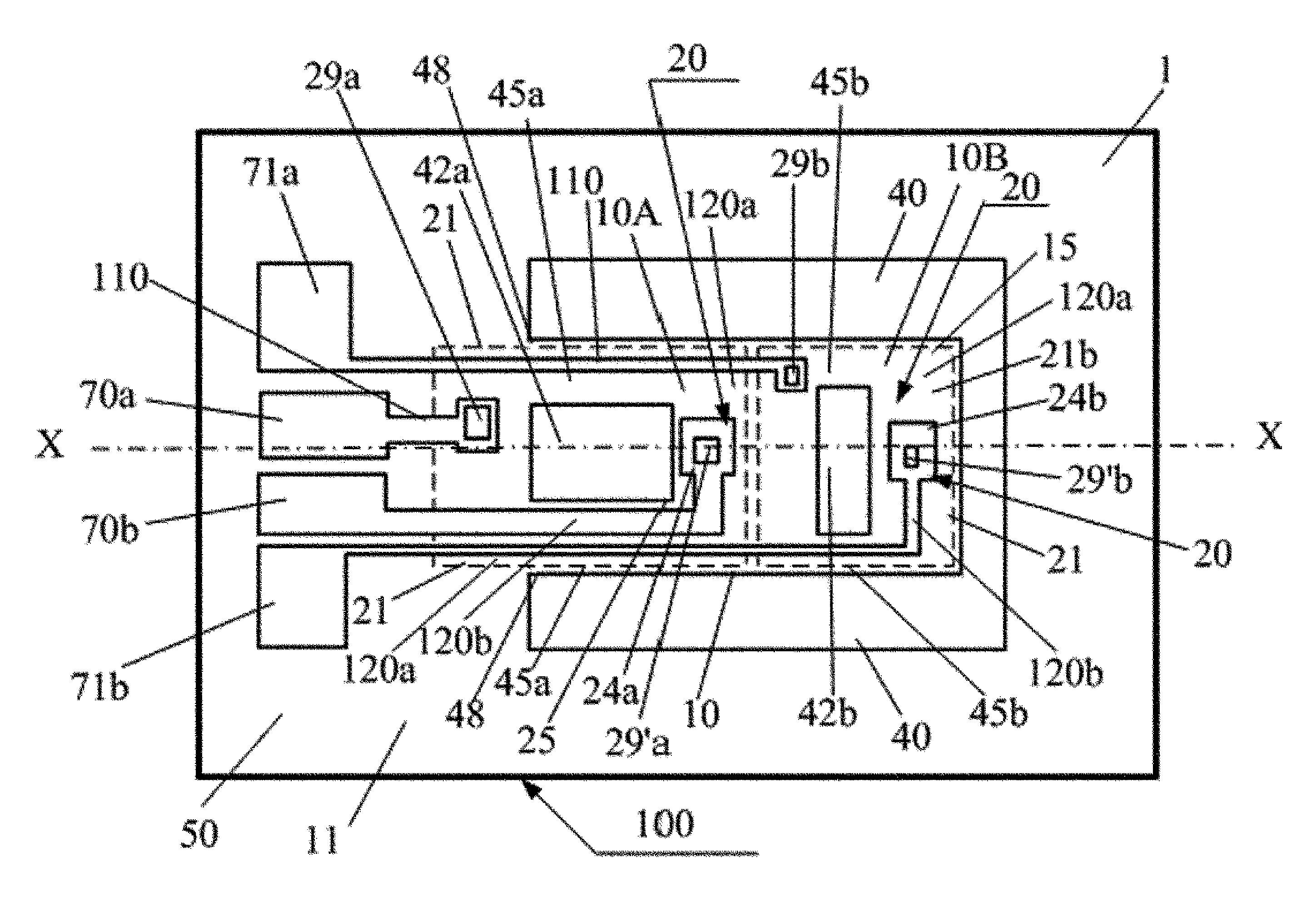
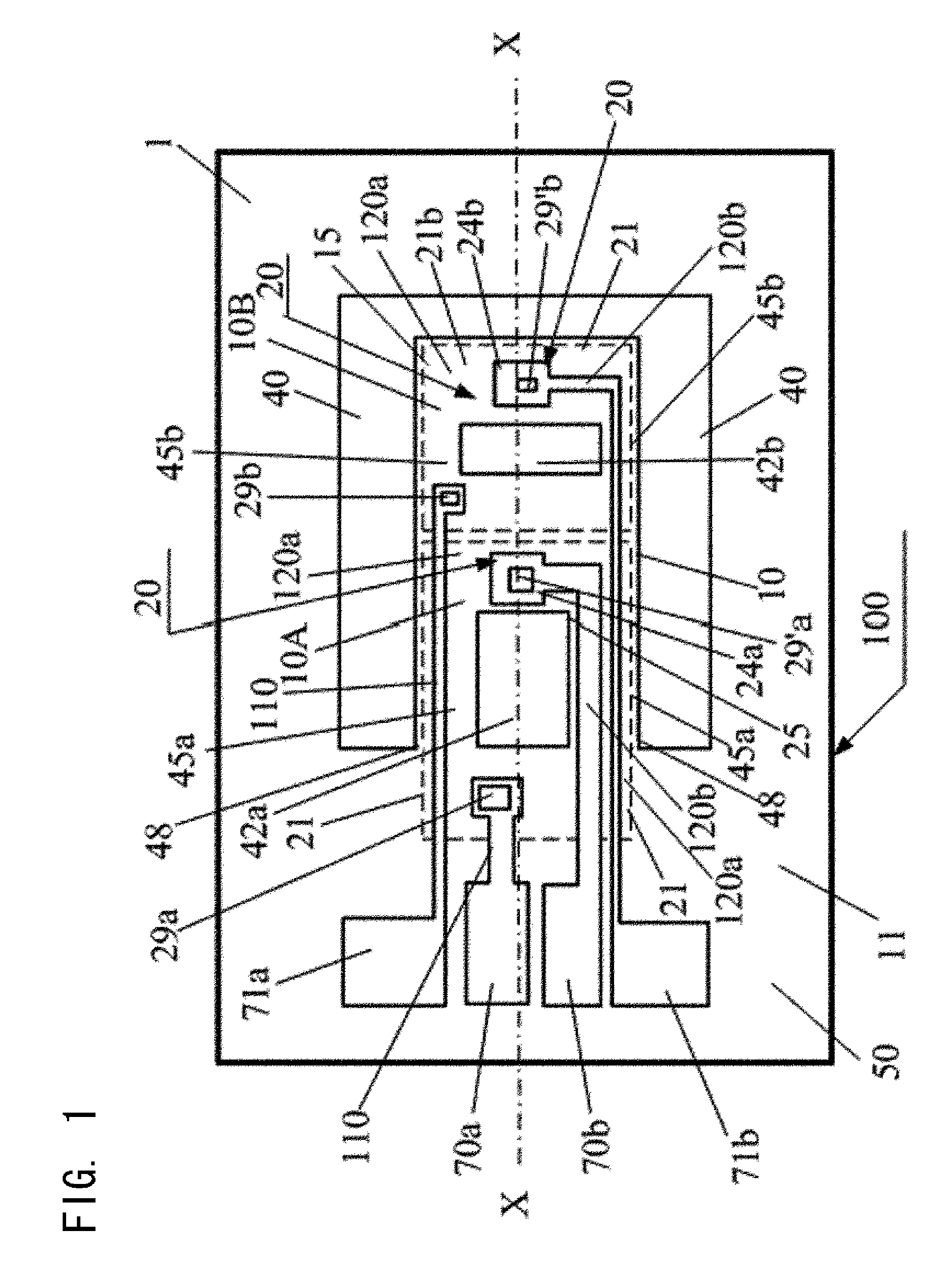
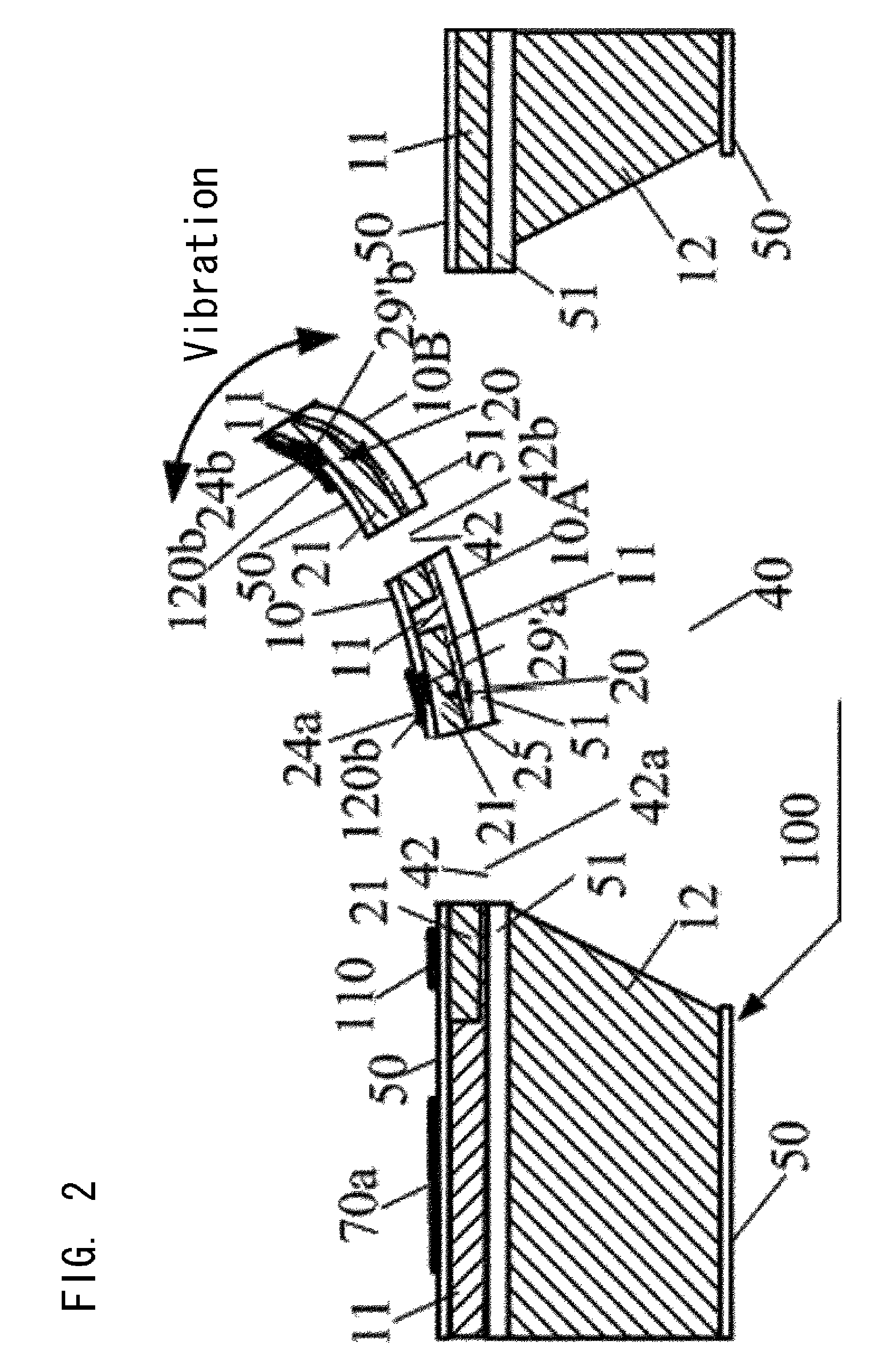
[0069]FIG. 1 relates to a heat conduction type barometric sensor according to the present invention and is a schematic plane view of an embodiment of the heat conduction type sensor chip 100 manufactured with the substrate 1 having an SOI layer, and further comprising a thin-film heater 25 as a heating means. Here, as a thin film 10 that is thermally separated from the substrate, a cantilever-shaped thin film (for example, 700 μm in length) is used which consists of two main layers of an SOI layer (for example, 10 μm in thickness) (Si layer) projected from the substrate 10 and a BOX layer (silicon oxide film layer) consisting of SiO2 layer (for example, 1 μm in thickness) below the SOI layer as a cantilever 15 in the cavity 40, and that said thin film 10 is divided into a thin film 10A and a thin film 10B. Further, an excitation means is formed to Bimorph-vibrate the cantilever 15 based on the difference in thermal expansion coefficients between the two layers. In addition, the thin...
second embodiment
[0076]FIG. 3 represents another embodiment of the heat conduction type barometric sensor chip 100 of the heat conduction type barometric sensor of the present invention, which is almost the same as that of FIG. 1. They are the same in forming a thermocouple 24a (thin-film temperature sensor (THA)) and a thermocouple 24b (thin-film temperature sensor (THB)) on the thin film (A) and the thin film (B), respectively, which are formed by dividing a thin film 10 that is thermally separated from a substrate by the intervention of the thermal resistance part 45b therebetween. However, the main differences are that the thin film 10 thermally separated from the substrate is designed such that a cold junction of the thermocouple that is the thermal reference is formed on the substrate 1; that the same electrode pad 70 is used for the sharing ohmic contact 29 as the cold junction of these two thermocouples; that a second thermocouple conductor 121a, 121b for each of the thermocouple 24a and the...
third embodiment
[0079]FIG. 4 relates to a heat conduction type barometric sensor according to the present invention and is a schematic plane view of another embodiment of the heat conduction type sensor chip 100 manufactured by using the substrate 1 such as silicon semiconductor, etc., and comprising a thin-film heater 25 as a heating means and a temperature sensor 20, wherein at least part of circuits required for operation of the heat conduction type barometric sensor are integrated in the same substrate 1. FIG. 4 illustrates that on the same substrate 1 of monocrystalline silicon, in addition to a sensing part 200 of the cantilever-shaped heat conduction type sensor having a thin-film heater 25 as a heating means and a temperature sensor 20, an amplifier (AMP) comprising an OP AMP amplifying signals relevant to barometric pressure to be measured from the temperature sensor such as a thermocouple, a power integrated circuit (Power IC) for supplying power to the thin-film heater, a memory circuit ...
PUM
| Property | Measurement | Unit |
|---|---|---|
| temperature coefficient of resistance | aaaaa | aaaaa |
| pressure | aaaaa | aaaaa |
| barometric pressure | aaaaa | aaaaa |
Abstract
Description
Claims
Application Information
 - R&D
- Intellectual Property
- Life Sciences
- Materials
- Tech Scout
- Unparalleled Data Quality
- Higher Quality Content
- 60% Fewer Hallucinations
Browse by: Latest US Patents, China's latest patents, Technical Efficacy Thesaurus, Application Domain, Technology Topic, Popular Technical Reports.
© 2025 PatSnap. All rights reserved.Legal|Privacy policy|Modern Slavery Act Transparency Statement|Sitemap|About US| Contact US: help@patsnap.com


