
Multifunctional radiation-hardened laminate

a radiation-hardened laminate and multi-functional technology, applied in the field of multi-functional composite structures, can solve the problems of imposing weight and instrument line of sight penalties on the craft, damage to the aircraft, and damage to the unprotected spacecraft, and achieves low distortion, high strength, and low weight

Active Publication Date: 2013-06-11
NORTHROP GRUMMAN SYST CORP
View PDF22 Cites 9 Cited by
  • Summary
  • Abstract
  • Description
  • Claims
  • Application Information

AI Technical Summary

Benefits of technology

[0008]A multifunctional composite having high strength, low weight, low distortion, low CTE, impact resistance, and multi-faceted radiation protection.

Problems solved by technology

For some types of aircraft, foreign objects will typically approach at velocities less than that of sonic velocity, approximately 0.3 km / second and cause damage to the aircraft.
For spacecraft, foreign objects may approach at a high velocity or hyper velocity, in the range of 10 to 72 km / second and cause damage to an unprotected spacecraft.
However, mechanical shields impose a weight and instrument line of sight penalty on the craft to which they are applied.
Foils formed of such materials used in composite structures incorporated into the walls of spacecraft, and the like, are costly to fabricate, and are prone to warpage or mechanical failure in use because the organic adhesive used between the metal foil and other materials of the composite structure each have different coefficients of thermal expansion.
Additionally, the adhesive bonds between dissimilar materials are not as robust as bonds between like materials and require proper processing.
However, composite structures formed of composite materials using thermosetting and thermoplastic polymer impregnated fiber reinforcement do not have sufficient surface conductivity with low resistant pathways for energy dissipation from lightning strikes or ESD.
Carbon / graphite fiber within the matrix offer higher conductivity than fiberglass materials or high temperature thermoplastic reinforced materials but are still deficient for energy dissipation from lightning strikes or ESD.
Composite structures on aircraft and spacecraft are subject to thermal stresses from both high temperatures and low temperatures.
Composite structures on aerospace vehicles are subject to aero-convective heating and radiant heating as well as being subject to launch acoustics, rain, and other elements of the environment.

Method used


Image

  • Multifunctional radiation-hardened laminate
  • Multifunctional radiation-hardened laminate
  • Multifunctional radiation-hardened laminate

Examples


first embodiment

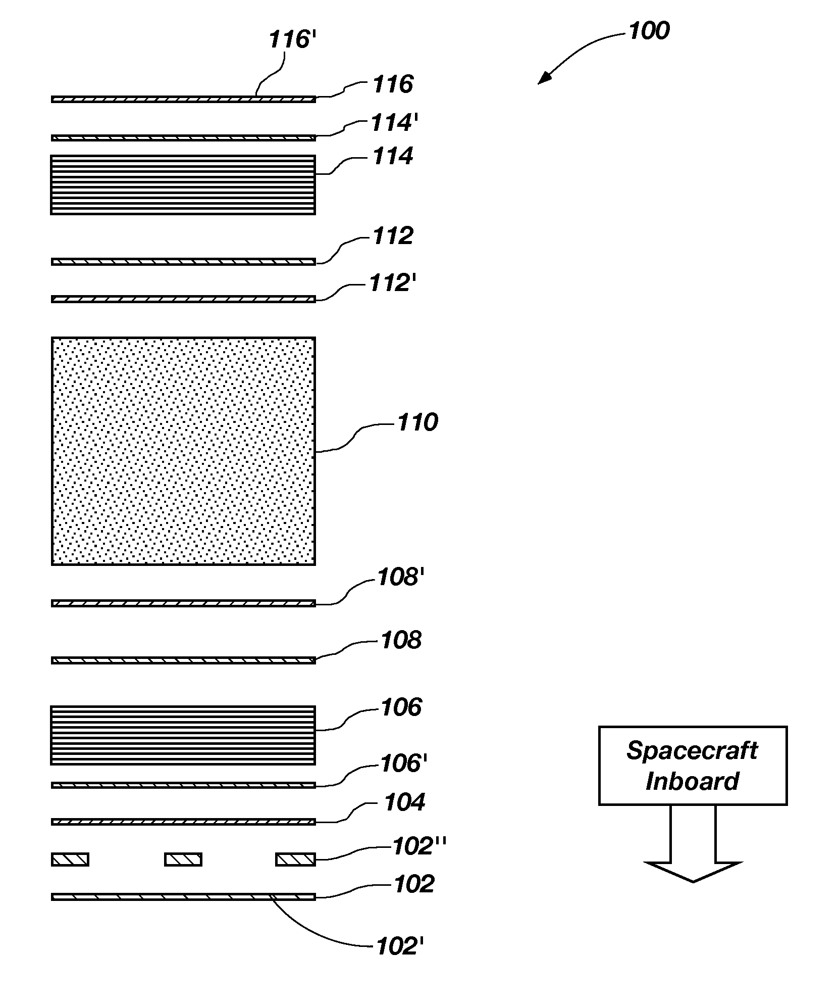
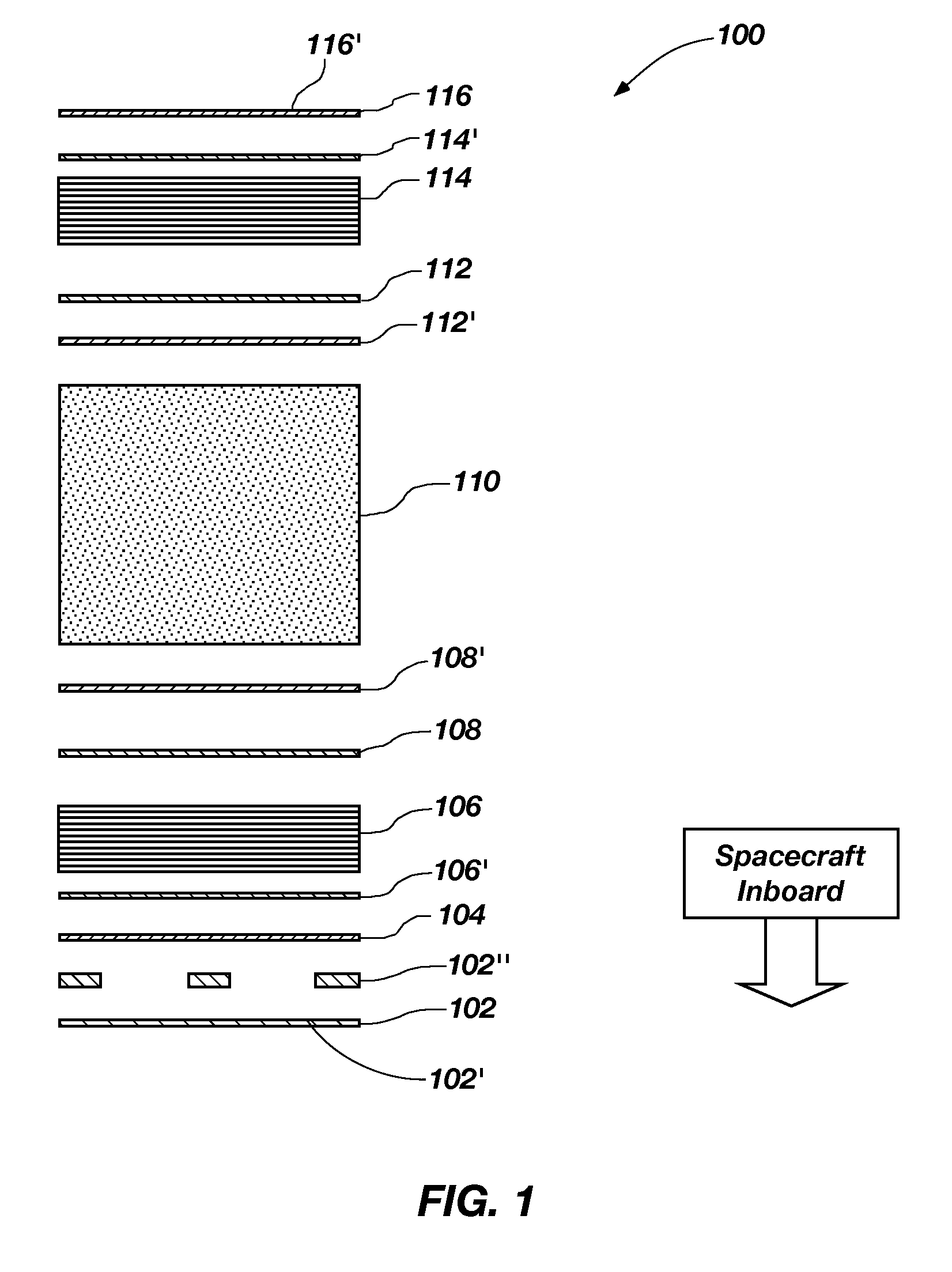
[0020]Referring to drawing FIG. 1, the composite structure 100 of the invention for use in forming flat cored panels which are radiation resistant, have high strength to weight, low distortion, and have high rigidity is illustrated in cross-section. The composite structure 100 comprises a laminate including various layers of materials. From the inboard of the spacecraft, a layer 102 of low modulus high density polyethylene comprising a film or fabric optionally hydrogenated and filled with carbon nano-tubes may be used with the layer 102, a metallized layer of aluminum 102′ may be disposed thereon. The thickness of the layer 102 of the high density polyethylene film or fabric and the thickness of the metallized layer of aluminum 102′ thereon may be any desired thickness to be determined by the environment, the loading, and the particular application in which the composite is to be used and is attached by thin epoxy layer 102″.

[0021]Located outboard of the layer 102 is a layer 104 of...

second embodiment

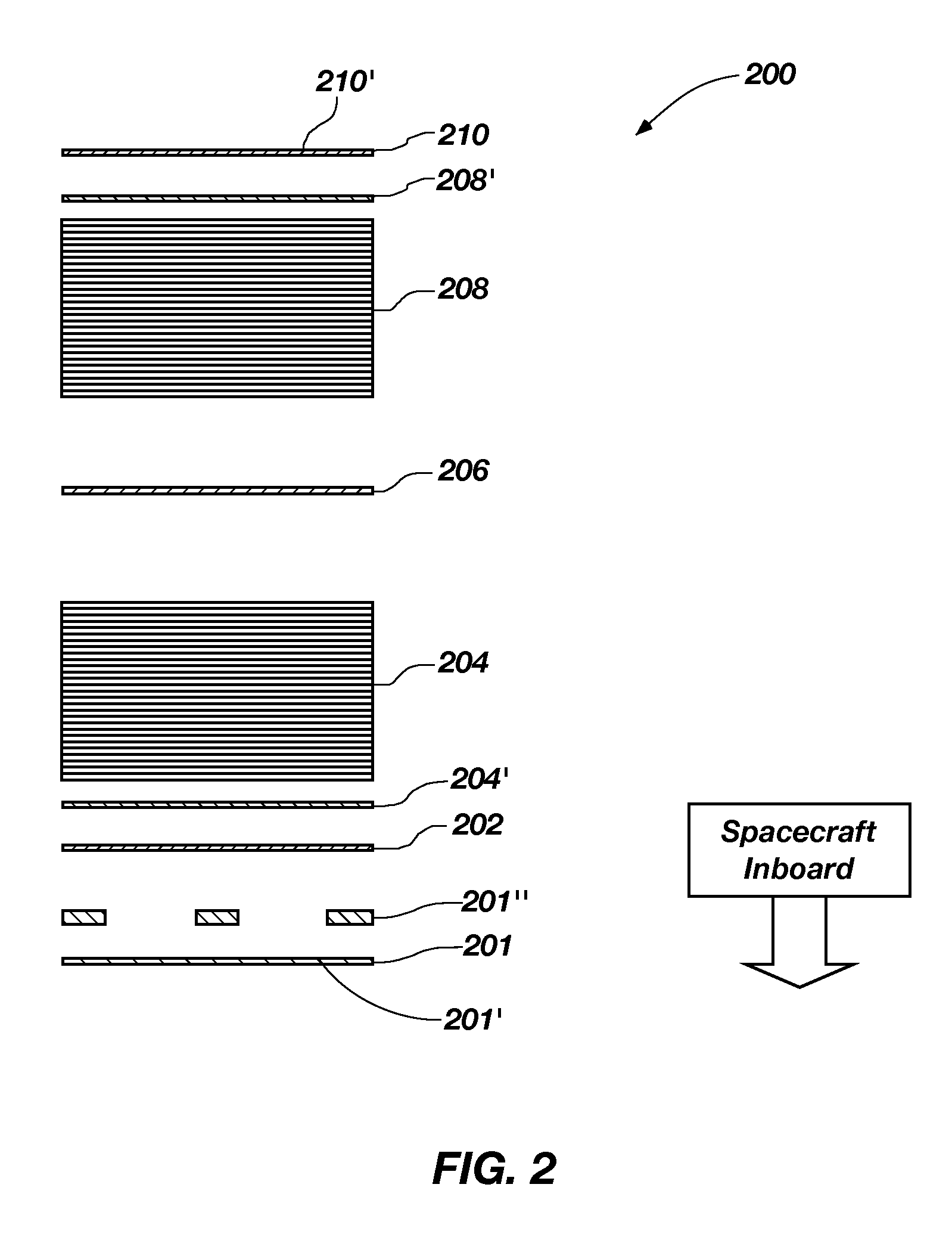
[0036]Referring to drawing FIG. 2, a composite structure 200 of the invention for use in forming an enclosed cylindrical or rhomboid tube-shaped laminate, which is radiation resistant, has high strength to weight, and has high rigidity is illustrated in cross-section. The composite structure 200 comprises a laminate including various layers of materials. From the inboard of the enclosed part, a layer 201 of low modulus high density polyethylene film or fiber fabric may be used, with the layer 201 optionally being hydrogenated and filled with carbon nano-tubes, or having a metallized layer 201′ disposed thereon. The thickness of the layer 201 of the high density polyethylene film or fiber fabric and the thickness of the metallized layer 201′ thereon may be any desired thickness to be determined by the environment, the loading, and the particular application in which the composite is to be used and is attached by a thin epoxy layer 201″.

[0037]Located outboard of the layer 201 is layer...

third embodiment

[0047]Referring to drawing FIG. 3, the composite structure 300 of the invention for use in forming layered flat boron separated laminate panels which are radiation resistant, have high strength to weight, and have high rigidity is illustrated in cross-section. The composite structure 300 comprises a laminate including various layers of materials. From the inboard of the spacecraft, a layer 302 of low modulus high density polyethylene film or fiber fabric may be used, with the layer 302 optionally being hydrogenated and filled with carbon nano-tubes, or having a metallized layer 302′ disposed thereon. The thickness of the layer 302 of the high density polyethylene film or fiber fabric and the thickness of the metallized layer thereon may be any desired thickness to be determined by the environment, the loading, and the particular application in which the composite is too used and is attached by a thin epoxy layer 302″.

[0048]Located outward of the layer 302 is a layer 304 of metallic ...


PUM

PropertyMeasurementUnit
sonic velocityaaaaaaaaaa
hyper velocityaaaaaaaaaa
thermal emissivityaaaaaaaaaa

Abstract

A multifunctional composite having high strength, low weight, low distortion, low CTE, impact resistance, and multi-faceted radiation protection.

Description

FIELD OF THE INVENTION[0001]This invention is related to multifunctional composite structures that are resistant to impact, radiation, thermal distortion, and thermal stresses.BACKGROUND[0002]Resistance to the effects of object impact, radiation, thermal distortion and thermal stresses are desirable in composite material laminates used in different types of structures where dimensional precision, high strength and light weight are preferred.[0003]It is desirable to have high strength lightweight composite structures that can be used on aircraft, spacecraft, satellites, missiles, and the like that are resistant to impact damage from various types of objects. For instance, aircraft and spacecraft need protection from impact with foreign objects, such as rain, birds, rocks, dirt, micro-meteoroids, and orbital debris. For some types of aircraft, foreign objects will typically approach at velocities less than that of sonic velocity, approximately 0.3 km / second and cause damage to the air...

Claims


Application Information

Patent Timeline
Patent Type & Authority Patents(United States)
IPC IPC(8): B32B3/12E04H7/22B32B5/12B32B27/00B32B5/16B32B9/04B32B15/00B32B37/04B32B5/02
CPCB32B15/08B32B15/14B32B27/38Y10T428/256Y10T428/24149Y10T428/24917Y10T428/254B32B5/02B32B5/024B32B5/22B32B5/26B32B7/12B32B15/20B32B27/18B32B27/32B32B3/12B32B2255/06B32B2255/26B32B2260/021B32B2260/046B32B2262/0269B32B2262/10B32B2262/106B32B2264/108B32B2307/30B32B2307/50B32B2307/558B32B2307/718B32B2605/00B32B2605/18Y10T442/198Y10T442/2508Y10T428/31504Y10T442/3545Y10T442/3594
Inventor LONG, DAVID S.
Owner NORTHROP GRUMMAN SYST CORP
Learn More