
Scalable monolithic single frequency fiber amplifier

a monolithic, single-frequency technology, applied in the field of optical fibers, can solve the problems of reducing the limiting the performance of the fiber, and increasing the sbs threshold through the decrease of length, so as to achieve a short effective length of the fiber, and reduce the sbs threshold

Inactive Publication Date: 2013-06-11
THE UNITED STATES OF AMERICA AS REPRESETNED BY THE SEC OF THE AIR FORCE
View PDF4 Cites 17 Cited by
  • Summary
  • Abstract
  • Description
  • Claims
  • Application Information

AI Technical Summary

Benefits of technology

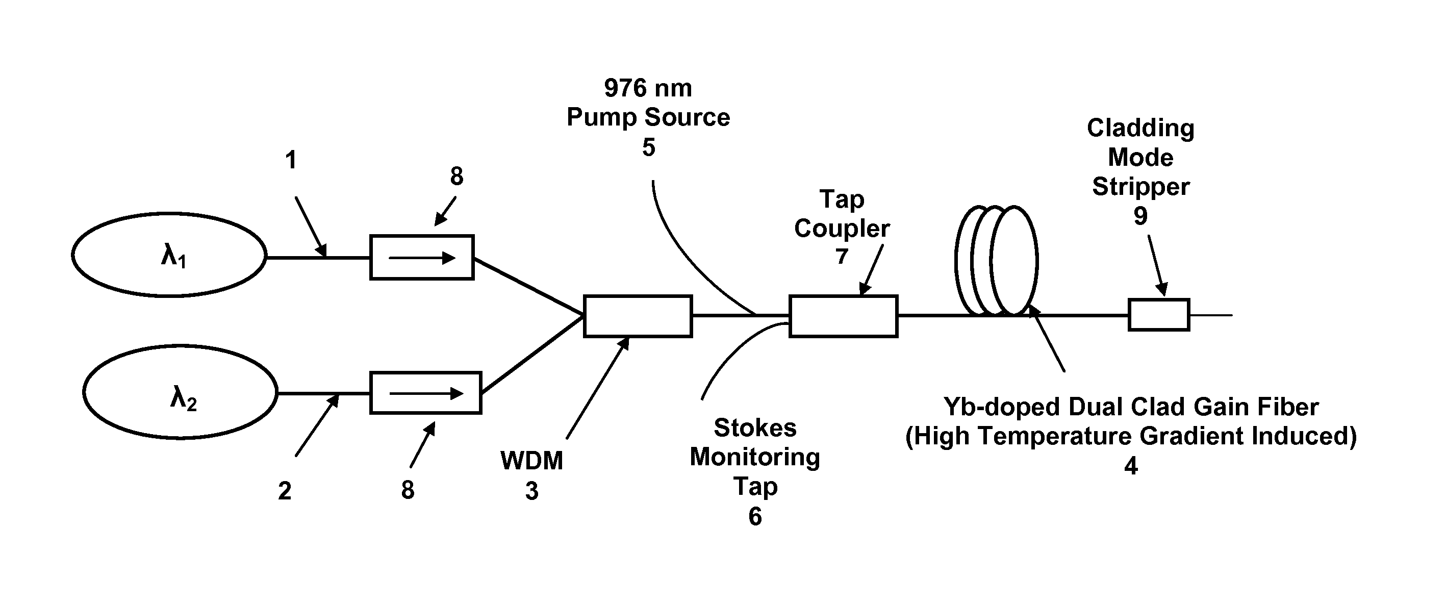
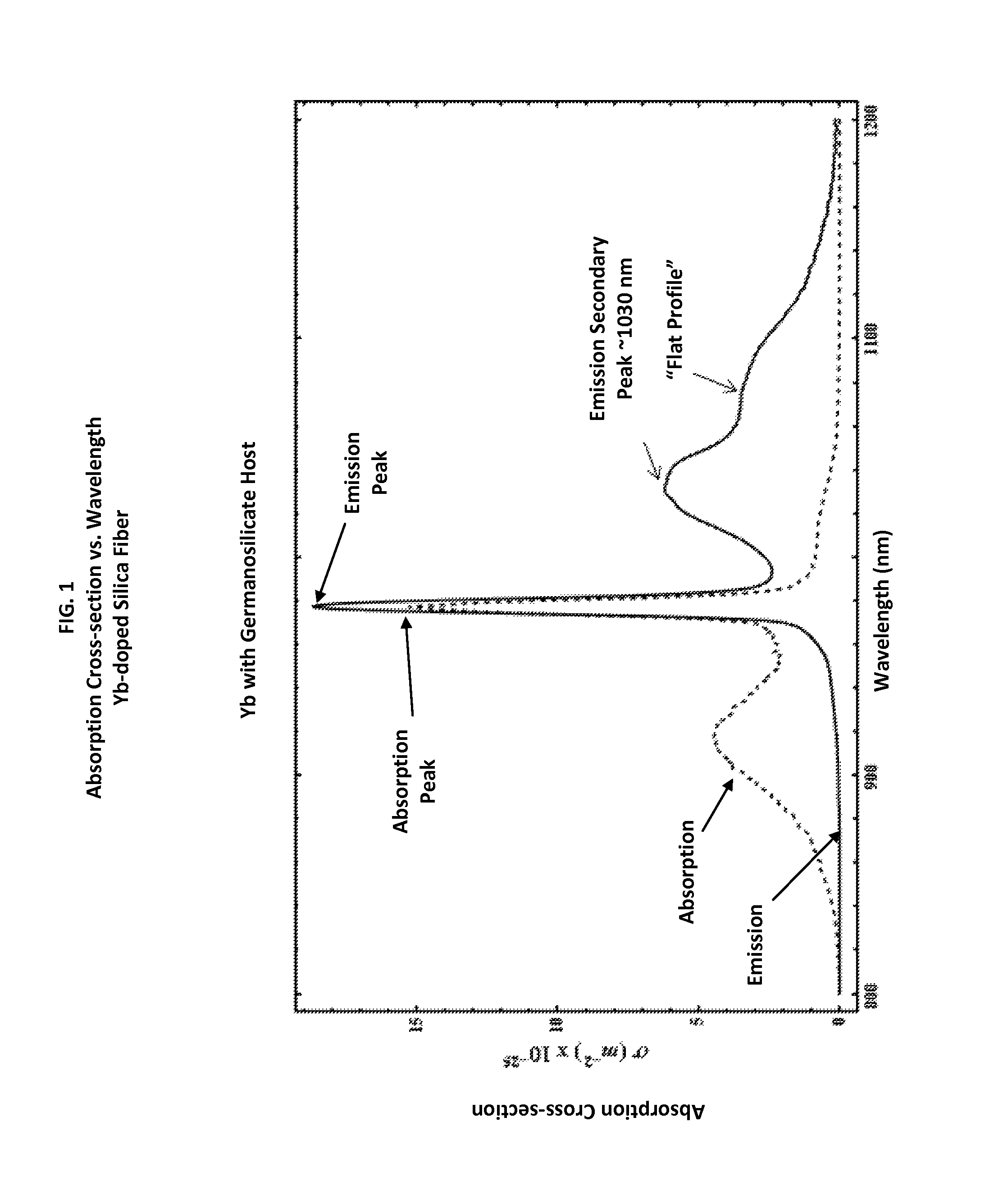
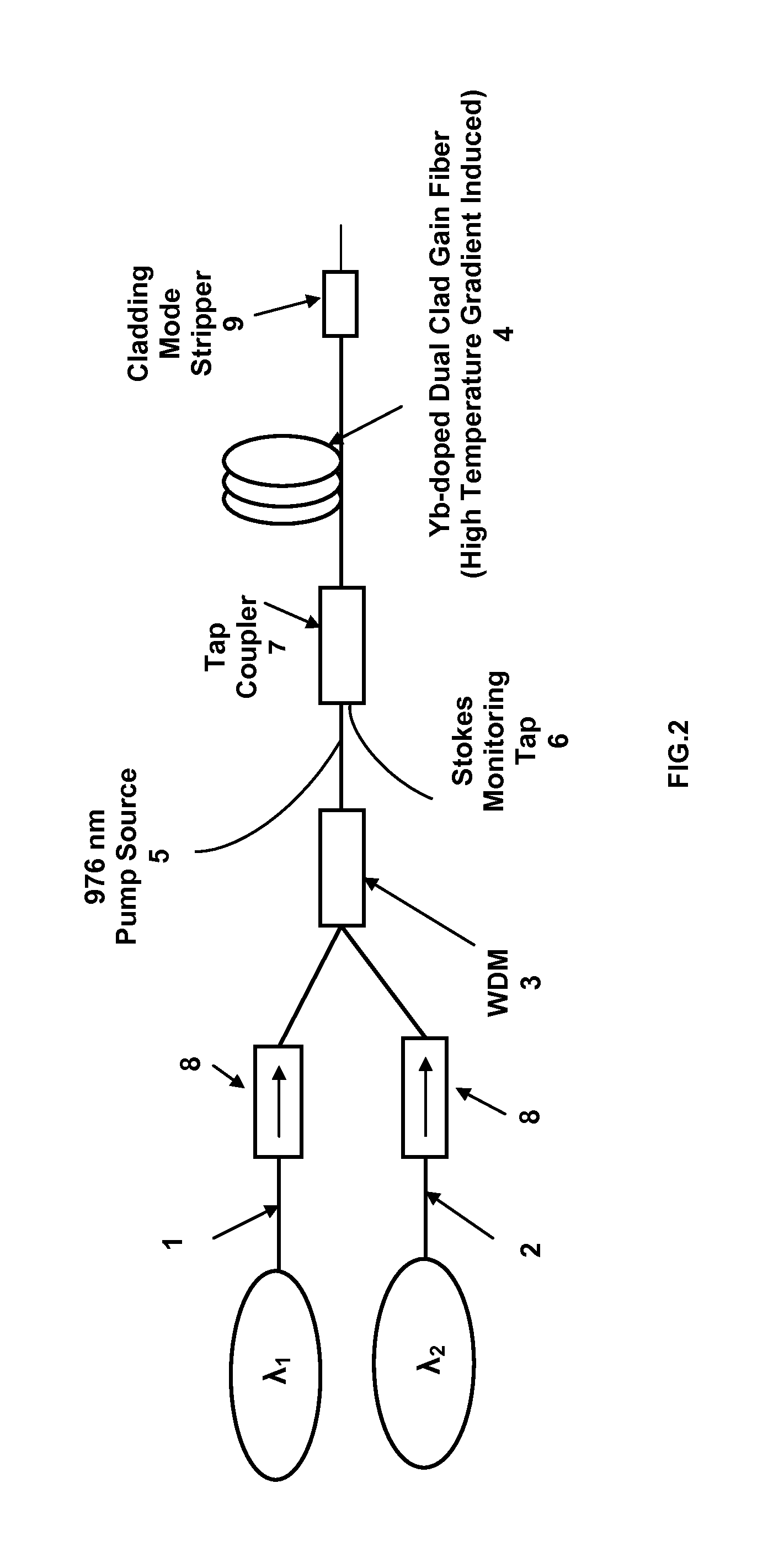
The invention is a new way to reduce SBS effects in fibers. It uses a special technique that involves combining two signals in a fiber. One signal has a shorter wavelength and greater emission and absorption cross sections than the other. The input power of the shorter signal is significantly greater than the other signal. Initially, both signals grow with distance along the fiber, but at a certain point, the shorter signal's power transfers to the other signal, effectively shortening the fiber's length and increasing the SBS threshold. In some cases, a U- or V-shaped temperature profile can be induced in the fiber to enhance SBS suppression. Overall, this technique offers a more effective way to reduce SBS effects in fibers.

Problems solved by technology

Stimulated Brillouin scattering (SBS) is a limiting factor in the evolution of rare-earth doped fiber lasers and amplifiers towards higher power.
It is well-known in the art that once a certain amount of optical power is coupled into or is generated in the fiber, significant backscattered Stokes light is produced causing the performance of the fiber to degrade.
The increase in the SBS threshold through the decrease of length is limited by either requirements for amplifier efficiency or rare-earth elements solubility in silica.
The technique is limited by the fact that a change in the draw tension leads to a change in the fiber diameter.
However, it does not appear based on theoretical analysis that this would yield any appreciable SBS suppression.
But so far, attempts to fully utilize a transverse acoustic gradient in conjunction with a longitudinal thermal gradient have not been fruitful.
While such a configuration is beneficial in suppressing SBS, it is not well-suited for monolithic all fiber configurations due to the exposure of pump combiners to the signal light.
Consequently, robust deployment of counter-pumped fibers in rugged environments is problematic.
Another important issue for the full utilization of thermal gradients is the operating temperature of the acrylate polymer in the outer cladding region or in the coating region of the fiber.
In other words, the polymer material will be damaged due to the heat generated in the core prior to the SBS threshold being reached.
One significant drawback of this technique is the requirement that the two seed signals have to be precisely tuned.
Another significant drawback is that at such a small frequency separation, a parasitic process known as four-wave mixing (FWM) is prominent, leading to the generation of several frequency sidebands.
This broadening of the optical power spectrum precludes the implementation of this method in fiber laser applications that require well-defined spectra such as coherent beam combining.
While this technique can result in tripling the output power of the narrow linewidth signal, the authors address neither the utility of developing a thermal gradient in the fiber in conjunction with the aforementioned technique nor provide a recipe for achieving a large thermal gradient.
While some of the foregoing patents and applications may describe techniques that can lead to improvement in the power output of narrow linewidth amplifiers, each can have limitations.

Method used


Image

  • Scalable monolithic single frequency fiber amplifier
  • Scalable monolithic single frequency fiber amplifier
  • Scalable monolithic single frequency fiber amplifier

Examples


examples

[0039]A double clad fiber with a core diameter of 25 μm and an inner cladding diameter of 400 μm. The outer cladding and fiber coating extends to 550 μm and is composed of a polymer material. The maximum operating temperature of the polymer is 150° C. Three cases are compared: I) a co-pumped single seed single frequency amplifier operating at 1080 nm; II) a counter-pumped single seed single frequency amplifier operating at 1080 nm; and III) a two signal co-pumped amplifier with the broadband signal at 1030 nm and the single frequency signal at 1080 nm. All fibers were 6.5 m in length and each of the cases was optimized to operate at the maximum SBS threshold by controlling the convective cooling coefficient, h, described above.

[0040]FIG. 3 shows plots of the evolution of the single frequency (narrow-linewidth) signals (1080 nm) along the length of the fiber. The output powers are normalized such that the output power from case I is equal to 1. Note that case II provided approximatel...


PUM


Abstract

A method to increase the output power of monolithic narrow-linewidth Yb-doped fiber amplifiers by suppressing simulated Brillouin scattering. The fiber amplifier employs a co-propagating geometry and is seeded with broad- (source 2) and narrow- (source 1) linewidth signals that are sufficiently different in wavelengths to allow for efficient gain competition and favorable temperature profile at the output end of fiber. The broadband seed signal possesses the higher emission and absorption cross sections. If source 2 is also given sufficiently greater input power than source 1, it will be amplified to its maximum value as the seed signals reach the middle portion of the gain fiber. Beyond that portion, the signal having the lower emission and absorption cross sections (signal 1) will continue to experience gain by power transfer from both signal 2 and the pump light, attaining a power output well beyond what the maximum output would have been had the amplifier been illuminated with a single frequency beam. Furthermore, if the two signals are carefully selected such that appreciable quantum defect heating occurs during the power transfer, a steep thermal gradient develops leading to even further increase in output power.

Description

STATEMENT OF GOVERNMENT INTEREST[0001]The conditions under which this invention was made are such as to entitle the Government of the United States under paragraph I(a) of Executive Order 10096, as represented by the Secretary of the Air Force, to the entire right, title and interest therein, including foreign rights.BACKGROUND OF THE INVENTION[0002]The present invention relates generally to optical fibers and in particular to narrow linewidth (single frequency) high-power continuous wave (CW) or quasi-continuous wave fiber lasers and amplifiers. This invention is related to co-pending patent application Ser. No. 12 / 198,308 filed Aug. 25, 2008.[0003]Stimulated Brillouin scattering (SBS) is a limiting factor in the evolution of rare-earth doped fiber lasers and amplifiers towards higher power. This phenomenon is a result of a third-order nonlinear process that causes the scattering of laser light by a travelling hypersonic acoustic grating. The latter is initiated from thermal noise....

Claims


Application Information

Patent Timeline
Patent Type & Authority Patents(United States)
IPC IPC(8): H01S3/00
CPCH01S3/06754H01S3/094007H01S3/1618H01S3/0809H01S2301/03
Inventor DAJANI, IYAD A.ZERINGUE, CLINT M.
Owner THE UNITED STATES OF AMERICA AS REPRESETNED BY THE SEC OF THE AIR FORCE
Learn More