Systems and methods for laser assisted sample transfer to solution for chemical analysis
a technology of laser assisted sample transfer and chemical analysis, applied in the field of system and method of surface sampling, can solve the problems that conventional laser desorption techniques can be limited in their ability to desorb and ionize analytes
- Summary
- Abstract
- Description
- Claims
- Application Information
AI Technical Summary
Benefits of technology
Problems solved by technology
Method used
Image
Examples
example 1
Reflective Geometry, Dual Capillary Sampling Probe
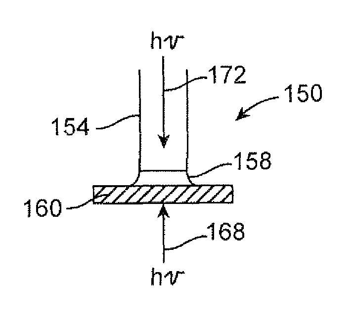
[0090]The reflective geometry data was gathered using an arrangement similar to that shown in FIG. 6. In the probe used in the examples, the outer diameter and inner diameter of the outer capillary were ˜635 μm and ˜330 μm, respectively, while the outer diameter and inner diameter of the inner capillary were ˜254 μm and ˜127 μm, respectively.
[0091]The laser beam was propagated through a 400 μm fiber optic cable and then passed through a 35 mm focusing lens onto the target site. The impingement angle (θ) was 45°, the laser beam wavelength was 337 nm and the fluence of the beam was 80 mJ / cm2. The solvent utilized was a 50:50 mixture of acetonitrile and water and the solvent flow rate was 13 μL / min.
[0092]FIG. 9 shows the mass spectrometer abundance versus m / z data where the specimen was rhodamine 6G, which has a molecular weight of 442 g / mol, on a glass slide. The data clearly shows the protonated form of rhodamine 6G at m / z=443 as the ...
example 2
Transmission Geometry, Dual Capillary Sampling Probe
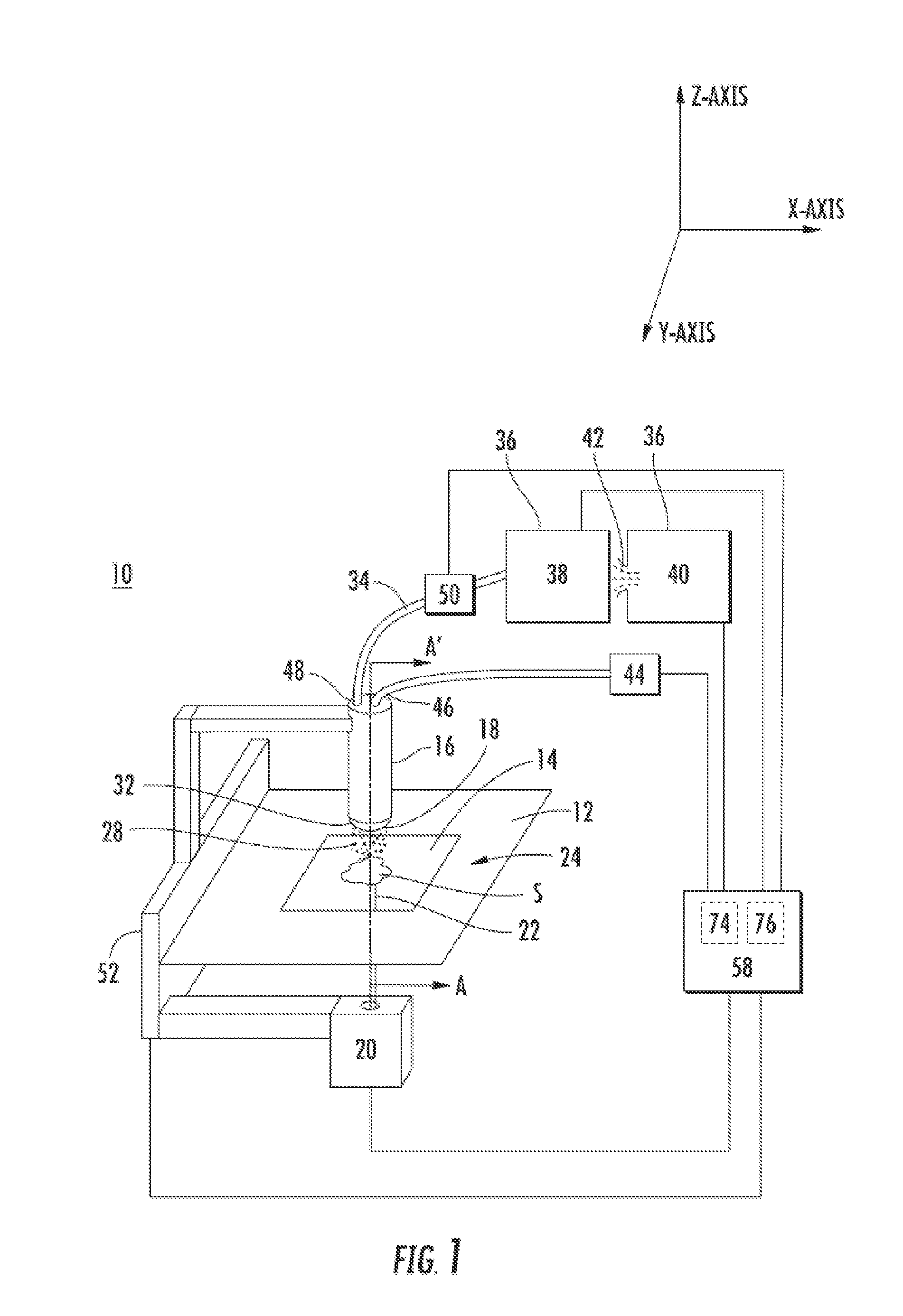
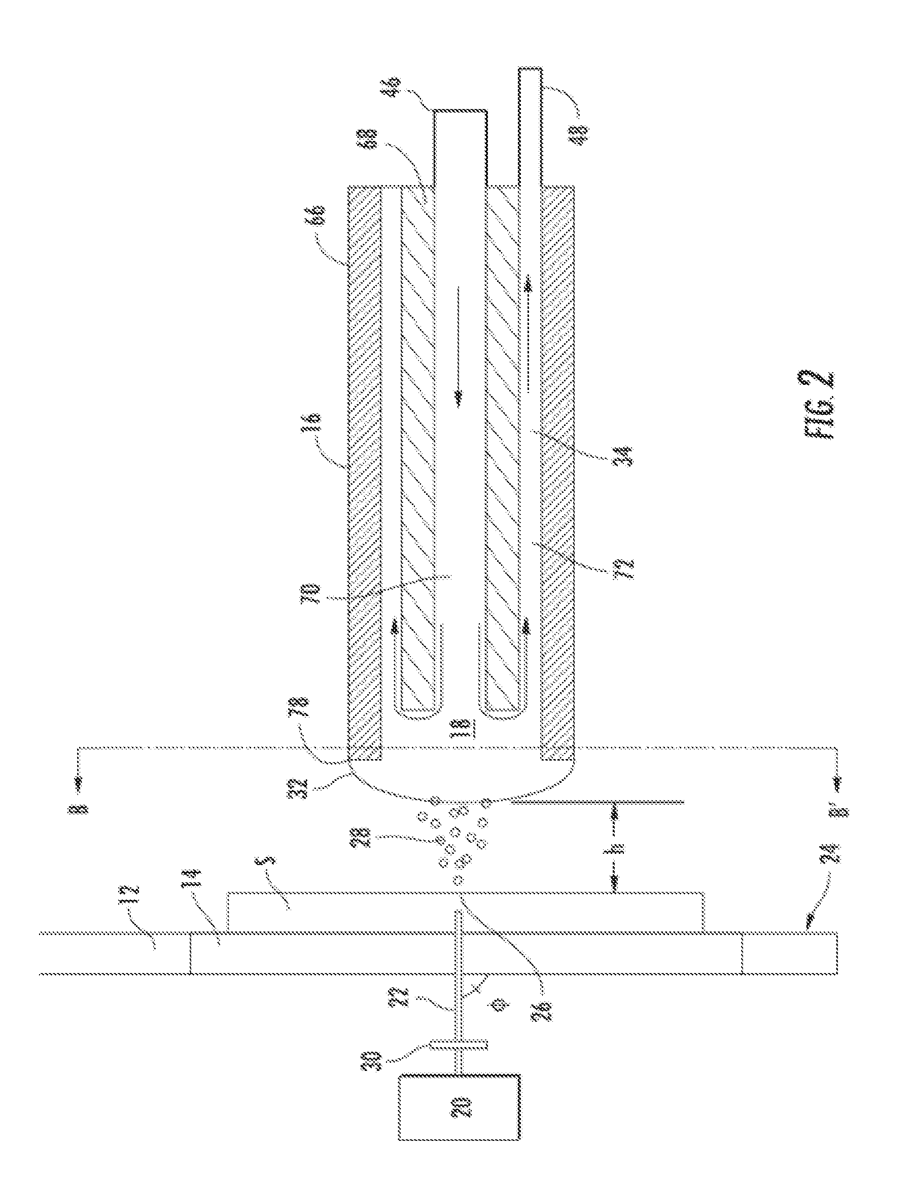
[0094]The transmission geometry data was gathered using an arrangement similar to that shown in FIG. 2. The laser beam was propagated through a 400 μm fiber optic cable and then passed through a 35 mm focusing lens toward the target site. The impingement angle (φ) was 90°, the laser beam wavelength was 337 nm and the fluence of the beam was 80 mJ / cm2. The probe tip was positioned 0.5 mm from the sample and the solvent utilized was a 50:50 mixture of acetonitrile and water. The specimen stage included a desorption region made of quartz and the energy transmitted through the quartz was 100 μJ.
[0095]FIGS. 11 & 12 shows the mass spectrometer intensity versus time data for a rhodamine 6G sample on a glass slide and a quartz slide, respectively. The rhodamine 6G signal level on glass was approximately 1.4×10⁸, while the signal level on quartz was approximately 3.2×10⁸. In contrast, the signal intensity for rhodamine 6G on a glass slide u...
example 3
Transmission Geometry, Single Capillary Sampling Probe
[0096]Sampling
[0097]This transmission geometry data was gathered using an arrangement similar to that shown in FIG. 3. The laser beam and focusing lens system was the same as that used in Example 2. The sampling probe was a 10 μL syringe loaded with 3 μL of solvent. The solvent composition was 49.95 / 49.95 / 0.1 water / acetonitrile / formic acid. The tip of the syringe was positioned 0.5 mm above the sample surface.
[0098]The laser was fired and 1 μL of solvent was dispensed from the syringe at a rate of 16 nL / sec, i.e., desorption step of approximately 1 minute. After the desorption step, the droplet hanging from the syringe tip was drawn into the syringe at a rate of 0.1 μL / sec for two (2) seconds. The testing solution in the syringe was then dispensed into an analytical instrument at a rate of 1 μL / s.
[0099]Mass Spectrometer Results
[0100]In the first part of this Example, testing solutions were collected both with and without the lase...
PUM
| Property | Measurement | Unit |
|---|---|---|
| incident angle | aaaaa | aaaaa |
| incident angle | aaaaa | aaaaa |
| incident angle | aaaaa | aaaaa |
Abstract
Description
Claims
Application Information
 - R&D
- Intellectual Property
- Life Sciences
- Materials
- Tech Scout
- Unparalleled Data Quality
- Higher Quality Content
- 60% Fewer Hallucinations
Browse by: Latest US Patents, China's latest patents, Technical Efficacy Thesaurus, Application Domain, Technology Topic, Popular Technical Reports.
© 2025 PatSnap. All rights reserved.Legal|Privacy policy|Modern Slavery Act Transparency Statement|Sitemap|About US| Contact US: help@patsnap.com


