Vertical wind power generator

a generator and wind power technology, applied in the direction of electric generator control, greenhouse gas reduction, sustainable manufacturing/processing, etc., can solve the problems of high maintenance cost, long maintenance time, affecting the working efficiency of the wind power generator

Active Publication Date: 2013-10-01
GUANGZHOU YATU NEW ENERGY TECH +1
View PDF3 Cites 6 Cited by
  • Summary
  • Abstract
  • Description
  • Claims
  • Application Information

AI Technical Summary

Benefits of technology

[0008]The aim of the present invention is to provide a vertical wind power generator. Using the structure of the present invention, the manufacturing cost of the vertical wind power generator can be reduced; when the generator is hard to start, it can be rapidly started; the size of the windward side of the blades can be adjusted, in order to automatically adjust the power of the wind power generator, prevent the failure of the wind power generator caused by excessive wind speed, and enhance the utilization efficiency of the wind energy; good cooing effect can be achieved on the generator, stability of the generator can be enhanced, and the operating life of the generator can be increased; it becomes easy to maintain, the maintenance cost and time can be reduced, and the detection to the generator is facilitated.

Problems solved by technology

Because such wind power generator is too big, the rotating shaft is usually high, in order to strengthen its stability, by dragline from the top of the rotating shaft to the bottom surface, even though the rotating shaft is strengthened, its occupied area is bigger, which undermines efficient use of the land; in addition, the power transmission chain is too long in the wind power generation process, therefore the power losses too much energy in the course of transmitting, which is not conducive to efficient use of energy; furthermore, only can the power generating device generate electricity when it comprises the gearbox, generator, transmission shaft and other sets of components, and the structure of the power generating device is complex, once the power generating device breaks down, its maintenance and repairs are too difficult and only can the large components be lift when erecting the tower crane besides the generator, therefore, the maintenance cost is high and the maintenance time is long, which directly affects the working efficiency of the wind power generator.
A large bearing causes high production costs, a bearing with a diameter of 5 m needs about 300-400 thousand, and that with a diameter of 3 m needs hundreds of thousands, on the other hand, it is not easy to assemble a large bearing.
In wind power generator, high and low utilization efficiency of wind power depends on the construction and the structure of the blade; nowadays, the shape of a blade of a vertical wind power generator varied, such as fan-shaped structure, the sail-shaped structure, φ-shaped structure, etc., in these structures, φ-shaped structure has the highest utilization efficiency of wind energy, but due to changes in wind speed and wind power is uncertain, resulting in the size of the windward side of the blade out of control, therefore, it's difficult to prevent the failure and even damage of the vertical wind power generator caused by excessive wind speed.
The generator will produce heat at work, in particular the high-power generator, if not cooling the generator, the generator will be burned, reducing the life of the generator.
Conducting the method of water cooling, it needs to layout a lot of waterway, which has complex structure and is difficult to achieve the required water seal, causing the damage of the motor insulation, and affecting the life of the motor; an outer rotor energy saving wind power generator is disclosed in Chinese patent of No. 200520032333.9, comprising an outer rotor, a stator, a fixing shaft and a bearing, the stator is fixed on the fixing shaft, the outer rotor is fixedly installed on the bearing through the upper and lower end cover by the magnet installed on the shell and inner wall, there are louvers on the two ends of said shell.
In this structure, because part of the heat of the generator evolutes through the louvers, there is no heat exchange in the whole structure, causing poor heat dissipation.

Method used


Image

  • Vertical wind power generator
  • Vertical wind power generator
  • Vertical wind power generator

Examples


first embodiment

The First Embodiment

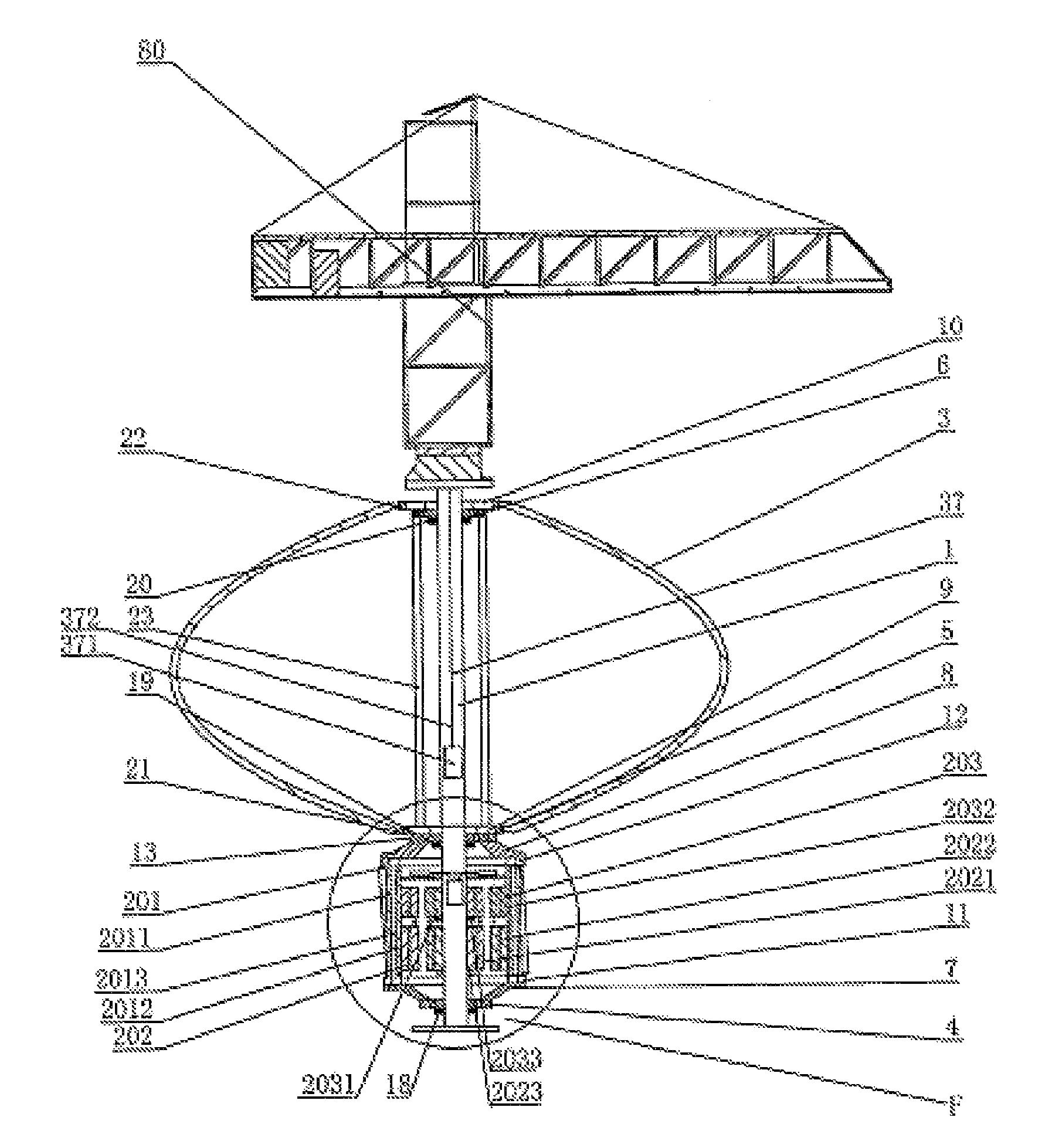
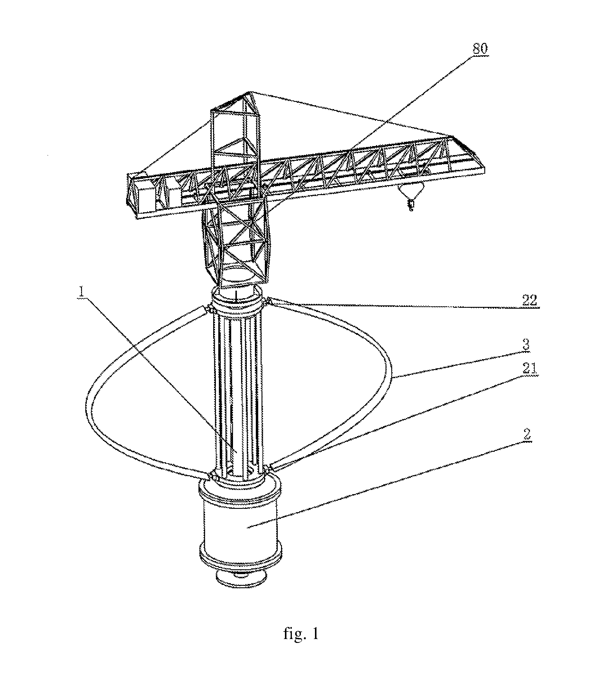
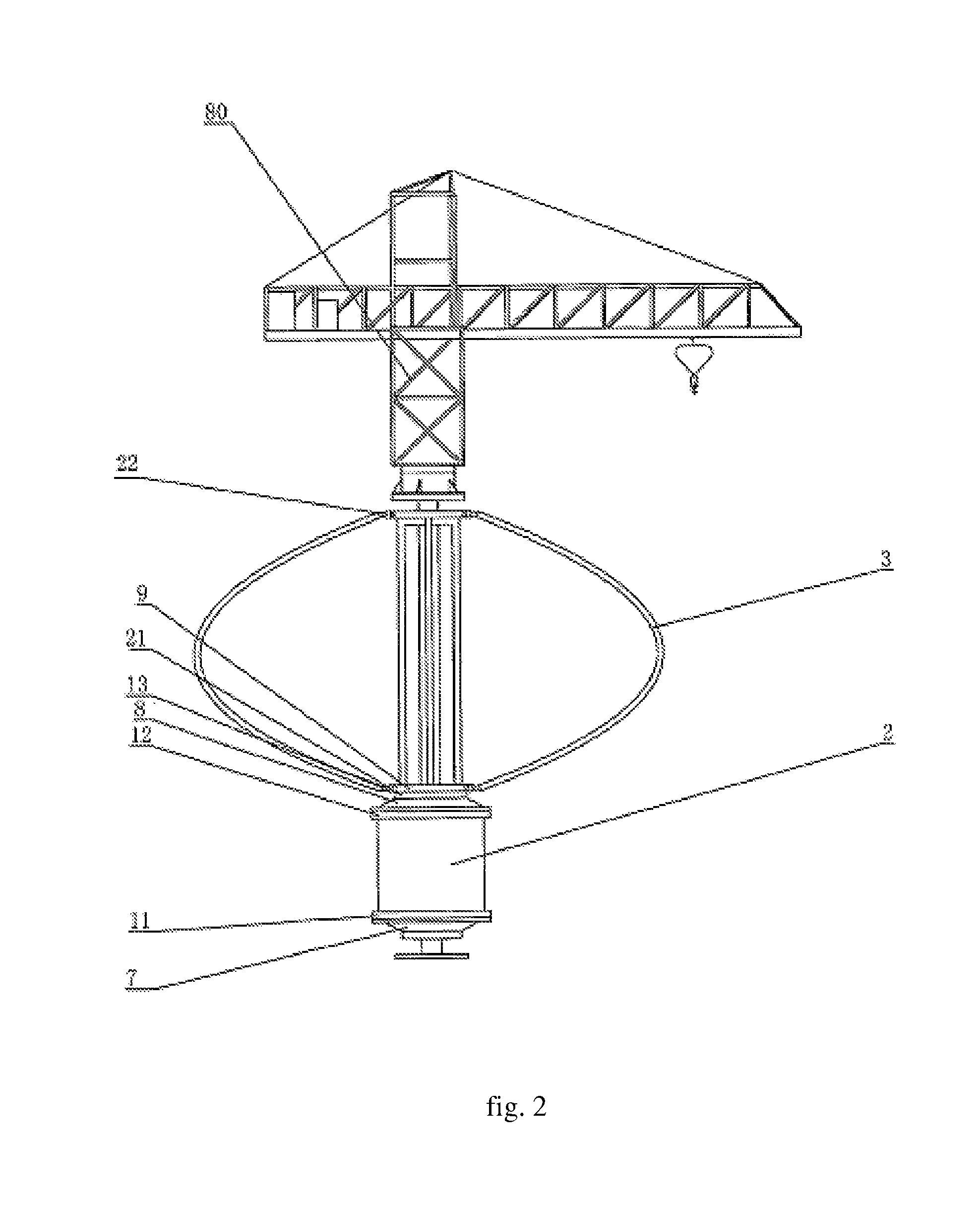
[0086]The vertical wind power generator as shown in FIG. 1 to FIG. 3, includes a tower column 1, at least one generator unit 2, at least two blades 3, a first bearing 4, a second bearing 5, a third bearing 6, a first flange 7, a second flange 8, a third flange 9, a fourth flange 10, a fifth flange 11, a sixth flange 12, and a seventh flange 13, and in this embodiment, the generator unit 2 is one, the blades 3 are two, the central axis of the tower column 1 is perpendicular to the horizontal plane, and the said tower column 1 is a hollow structure.

[0087]As shown in FIG. 3 and FIG. 4, the said generator unit 2 comprises a bracket 201, a generator 202 and an exciter 203.

[0088]See FIG. 3 and FIG. 4, the said bracket 201 is comprised of an outer bracket 2011 and an inner bracket 2012, the outer bracket 2011 is provided outside the inner bracket 2012, and a bracket duct 2013 is formed between the outer bracket 2011 and the inner bracket 2012.

[0089]See FIG. 3 and FIG. 4...

second embodiment

The Second Embodiment

[0111]The vertical wind power generator as shown in FIG. 1 to FIG. 3, includes a tower column 1, at least one generator unit 2, at least two blades 3, a first bearing 4, a second bearing 5, a third bearing 6, a first flange 7, a second flange 8, a third flange 9, a fourth flange 10, a fifth flange 11, a sixth flange 12, and a seventh flange 13, and in this embodiment, the generator unit 2 is one, the blades 3 are two, the central axis of the tower column 1 is perpendicular to the horizontal plane, and the said tower column 1 is a hollow structure.

[0112]As shown in FIG. 3 and FIG. 4, the said generator unit 2 comprises a bracket 201, a generator 202 and an exciter 203.

[0113]See FIG. 3 and FIG. 4, the said bracket 201 is comprised of an outer bracket 2011 and an inner bracket 2012, the outer bracket 2011 is provided outside the inner bracket 2012, and a bracket duct 2013 is formed between the outer bracket 2011 and the inner bracket 2012.

[0114]See FIG. 3 and FIG. ...

third embodiment

The Third Embodiment

[0135]The vertical wind power generator as shown in FIG. 1 to FIG. 3, includes a tower column 1, at least one generator unit 2, at least two blades 3, a first bearing 4, a second bearing 5, a third bearing 6, a first flange 7, a second flange 8, a third flange 9, a fourth flange 10, a fifth flange 11, a sixth flange 12, and a seventh flange 13, and in this embodiment, the generator unit 2 is one, the blades 3 are two, the central axis of the tower column 1 is perpendicular to the horizontal plane, and the said tower column 1 is a hollow structure.

[0136]As shown in FIG. 3 and FIG. 4, the said generator unit 2 comprises a bracket 201, a generator 202 and an exciter 203.

[0137]See FIG. 3 and FIG. 4, the said bracket 201 is comprised of an outer bracket 2011 and an inner bracket 2012, the outer bracket 2011 is provided outside the inner bracket 2012, and a bracket duct 2013 is formed between the outer bracket 2011 and the inner bracket 2012.

[0138]See FIG. 3 and FIG. 4...


PUM


Abstract

A vertical wind power generator comprises a tower column (1), at least one generator unit (2), at least two blades (3), an excitation control device (16), a rotation rectifying device (161), a bidirectional frequency converter (15), flanges (7-13), bearings (4-6), a cooling system, a crane (80) and a lift system. The generator unit (2) comprises a bracket (201), a generator (202) and an exciter (203). The bracket (201) comprises an outer bracket (2011) and an inner bracket (2012). The generator (202) comprises a stator (2021) and a rotor (2022). The exciter (203) comprises a stator (2031) and a rotor (2032). The vertical wind power generator can be manufactured at reduced cost, be rapidly started, improve the utilization efficiency of wind power, have a better cooling effect on the generator (202) and increase its operating life, and therefore reduce maintenance cost and time.

Description

TECHNICAL FIELD[0001]The present invention relates to a vertical wind power generator.BACKGROUND[0002]Nowadays, non-renewable energy resources are becoming less and less, and even some energy has been consumed, therefore, as wave energy, combustible ice, coal bed gas and microbes, these energy sources will become the new energy widely used by human. Wind power, as a renewable energy, has been brought into use in many areas and equipment, and its technology is becoming mature slowly. Modern wind power generator mainly comprises horizontal axis wind power generator and vertical axis wind power generator. Vertical axis product and horizontal axis product are different. In vertical axis wind power generator, the rotating shaft is installed on the vertical axis, perpendicular to the ground, not affected by the wind direction when the vertical axis wind power generator are working, so no adjustment are required when the wind direction changes.[0003]Wherein, Darrieus turbine belongs to one...

Claims


Application Information

Patent Timeline
Patent Type & Authority Patents(United States)
IPC IPC(8): F03D9/00H02P9/04
CPCF03D3/005F03D11/00H02K7/183H02K9/04H02K19/38F03D11/0075F03D11/04F03D3/02F03D3/065F03D9/002F05B2260/201H02K16/00Y02E10/74Y02T50/675Y02E10/728F05B2240/212F05B2240/31F05B2240/912F05B2240/916F03D80/88F03D13/20F03D9/25F03D80/60F03D80/70Y02P70/50Y02T50/60F03D3/062F03D80/00
Inventor DENG, YUNHE
Owner GUANGZHOU YATU NEW ENERGY TECH
Why Eureka
Try Eureka