Surface-mount type overcurrent protection element

a protection element and surface mount technology, applied in the direction of resistor details, resistors adapted for applying terminals, positive temperature coefficient thermistors, etc., can solve the problems of device failure, too difficult to get a low room temperature resistivity of conductive filler materials, etc., to achieve good environmental stability and resistivity value

Active Publication Date: 2013-11-05
SHANGHAI CHANGYUAN WAYON CIRCUIT PROTECTION CO LTD
View PDF8 Cites 6 Cited by
  • Summary
  • Abstract
  • Description
  • Claims
  • Application Information

AI Technical Summary

Benefits of technology

[0005]It is an object of this invention to provide a surface-mount type over-current protection element with not only low resistance subsize high carrying current and PTC behavior but also good environmental stability.
[0046]Because there are the isolating layers around PTC material of the surface-mount type over-current protection element of the present invention to isolate PTC material from the outside oxygen and moisture, so that the resistance value will not increase obviously with the increasing of temperature or after a long while, which proves good environmental stability.

Problems solved by technology

But the conductive polymer using the black carbon as the conductive filler material is too difficult to get a low room-temperature resistivity, particularly using the polymer to make the over-current protection device of batteries can't satisfy the requirements of the miniaturization (e.g. size 1210, and the device area is 0.12″×0.10″, changing to the metric unit is 3.4 mm×2.75 mm) and the low resistance at room temperature (The typical resistance value of the zero power is 5 mΩ, and the resistance value is less than 15 mΩ after welded.).
But there is a new problem: general metal powder is very easy to be oxidized, particularly the oxidizing reaction will speed up in hot environment, which is the cause of the increasing resistance of the device, and it will lead the device to the failure.

Method used


Image

  • Surface-mount type overcurrent protection element
  • Surface-mount type overcurrent protection element
  • Surface-mount type overcurrent protection element

Examples


Embodiment Construction

[0060]The manufacturing method of the surface-mount type over-current protection element, comprising:

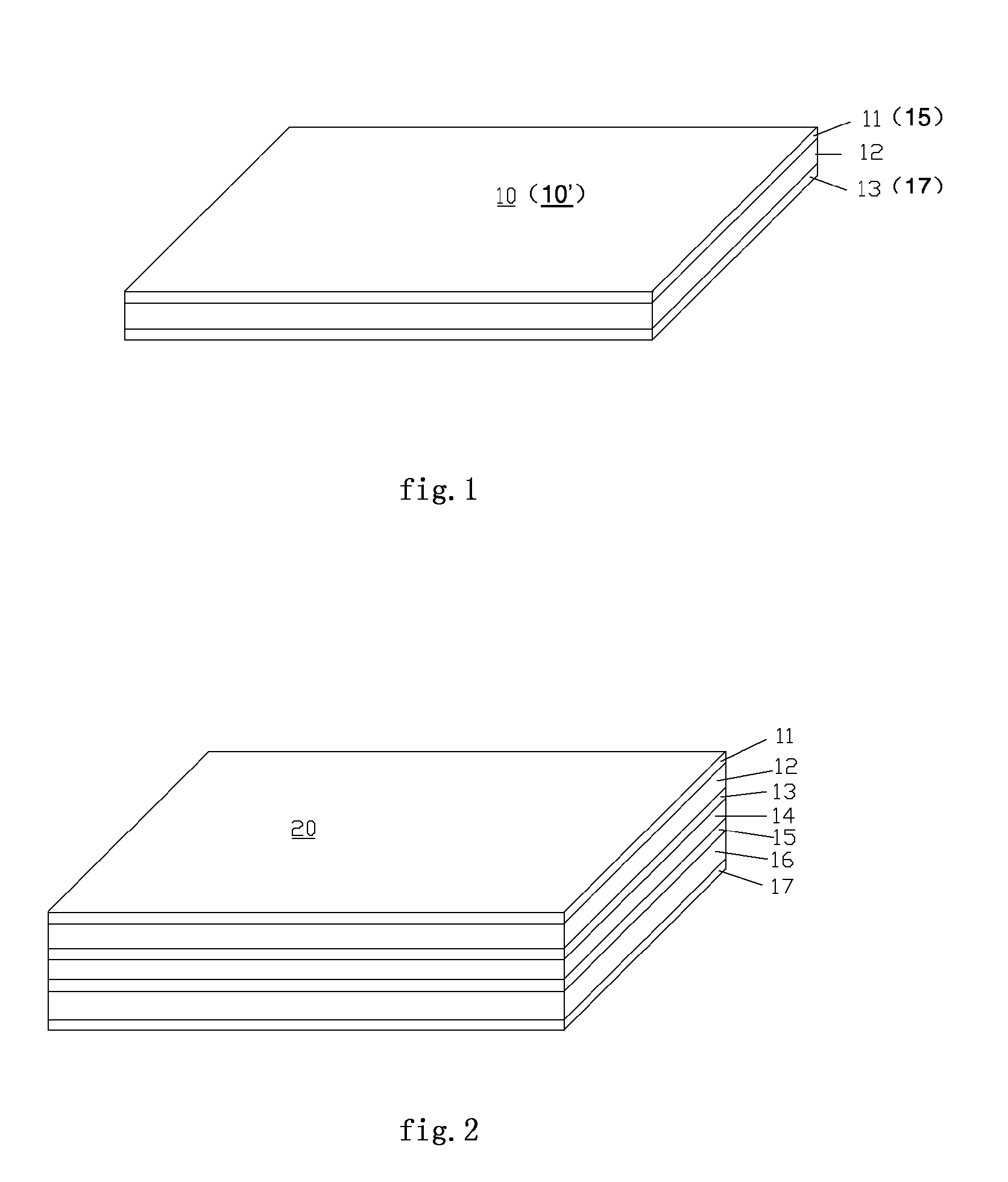
[0061]The first step: Mixing 100 units high density polyethylene (BHB5012, Phillips fossil oil), 500 units nickel powder (CNP525, INCO), 30 units magnesium hydrate and 0.5 units processing aid well at 190 in the internal mixer, then pulling out the first PTC chip material 12 and the second PTC chip material 16 from the open mill, whose thickness are 0.35 min±0.05 mm. Pasting the first metal foil layer 11 and the second metal foil layer 13 on both upper and lower surfaces of the first PTC chip material 12 and pasting the third metal fail layer 15 and the fourth metal foil layer 17 on both upper and lower surfaces of the second PTC chip material 16, then press them into one chip to get the single-layer PTC multiple chips 1010′, whose thickness are 0.35 mm±0.05 mm. FIG. 1 illustrates the structure diagram of the single-layer PTC multiple chips;

[0062]The second step: Putting the third in...


PUM

PropertyMeasurementUnit
resistanceaaaaaaaaaa
thicknessaaaaaaaaaa
resistanceaaaaaaaaaa

Abstract

A surface-mount type over-current protection element includes two single-layer composite chips, wherein one chip is made of a first core material and a first and a second metallic foil layer attached on the two surfaces of the first core material, the other chip is made of a second core material and a third and a fourth metallic foil layer attached to the two surfaces of the second core material. The protection element also has an insulating layer arranged between the two chips to electrically insulate and bond to the second and third metallic layers to form a bi-layer composite chip. Part of the first metallic foil layer and the corresponding part of the fourth metallic foil layer are etched to expose part of the first core material and correspond part of the second core material. One or more through-holes are made on the bi-layer composite chip for mounting.

Description

FIELD OF THE INVENTION[0001]The present invention relates to a surface-mount type over-current protection element, and more particularly to a over-current protection element with low resistance subsize and positive thermal coefficient (PTC) behavior.BACKGROUND OF THE INVENTION[0002]It was apparent to us that the conductive polymer made of polymer and conductive filler material dispersed in the polymer, and the technique of manufacturing the conductive polymer into the over-current protection device with PTC behavior. Generally, PTC conductive polymer is made of a kind of or more kinds of crystalline polymer and a kind of conductive filler material and the conductive filler material dispersed in the polymer. The polymer can be a kind of or the mixture of more kinds of polyethylene vinyl copolymer and fluoropolymer: The conductive filler material can be black carbon metal particles or inorganic ceramic powder. The PTC behavior of the conductive polymer the resistance value increase wi...

Claims


Application Information

Patent Timeline
Patent Type & Authority Patents(United States)
IPC IPC(8): H01C7/10
CPCH01C7/02H01C17/28H01C1/1406Y10T29/49082
Inventor LIU, ZHENGPINGLIU, YUTANGWANG, JUNYANG, JINHUAGAO, DAOHUACHENG, ZHENLI, QUANTAOSUN, TIANJU
Owner SHANGHAI CHANGYUAN WAYON CIRCUIT PROTECTION CO LTD
Why Eureka
Try Eureka