
Miniature optical elements for fiber-optic beam shaping

a technology of fiber-optic beam shaping and miniature optical elements, applied in the direction of instruments, catheters, angiography, etc., can solve the problems of low-cost manufacturing of miniature optical devices, excessive manufacturing costs, and excessive size, so as to improve manufacturing repeatability and prevent disruption or damage to sensitive samples

Active Publication Date: 2013-11-12
LIGHTLAB IMAGING
View PDF113 Cites 78 Cited by
  • Summary
  • Abstract
  • Description
  • Claims
  • Application Information

AI Technical Summary

Benefits of technology

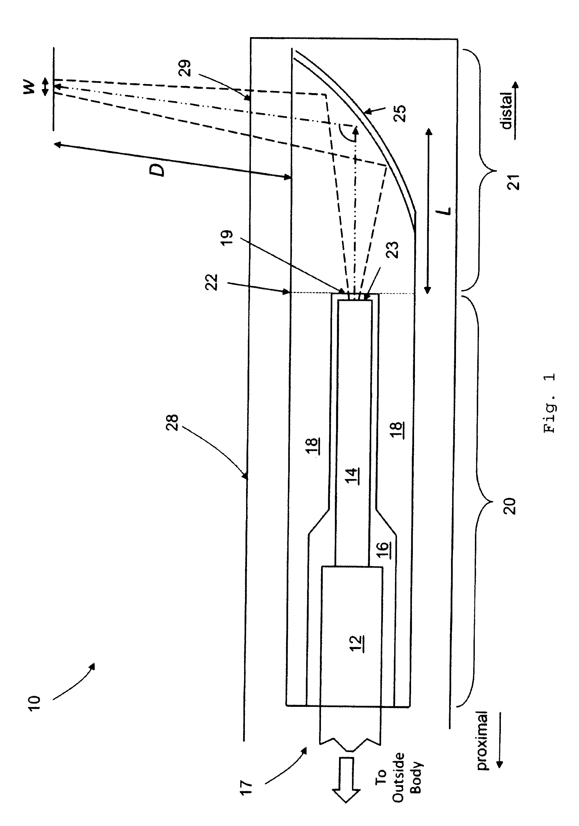
[0010]In part, the present invention provides a unitary optical element (or cap) having an internal cavity that slides over the end of an optical fiber for internal or external analysis of a sample. The cap includes integrated surface features for altering the beam direction as well as focusing or collimating the light to a prescribed width at a prescribed distance away from the cap. The cap is sufficiently small to prevent disruption or damage to sensitive samples, such as internal body tissue or luminal organs. Since the cap is a single monolithic element in an embodiment, it can be fabricated using low-cost methods such as injection molding. A significant cost advantage and improvement in manufacturing repeatability compared to previously-described methods is achieved.

Problems solved by technology

Due to the size and complexity of many light sources and light analysis devices, they are typically located remotely from the sample of interest.
A significant barrier to conducting optical analysis of internal regions, such as lumens, is the design and low-cost manufacture of miniature optical devices for focusing or collimating light.
These methods, however, have numerous inherent limitations, including excessive manufacturing cost, excessive size, or insufficient freedom to select the focal spot size and focal distance.
Several features of existing optical systems are undesirable.
This greatly reduces the options available for selecting the focusing element, beam expander, and beam director and therefore limits the range of focal spot sizes and working distances achievable by the design.
Additionally, these extremely small elements are fragile, difficult to handle, and prone to break during manufacturing and operation.
This can be problematic when the device is immersed in water, blood, or stomach acid, or when the device is rotated or translated at high speed in order to form an image.
Fourth, GRIN focusing elements have refractive index profiles that are rotationally symmetric, making it impossible to correct for cylindrical aberrations induced on the beam.
The overall effect of these drawbacks is that certain miniature optical systems are expensive, difficult to manufacture, prone to damage, and do not produce a circular output at the focal plane.
In addition to the drawbacks listed above, conventional lensed surfaces can only provide small radii of curvature and are largely limited to spherical geometries.
Additionally, the beam cannot expand to a size significantly larger than the single mode fiber diameter (often 125 μm) at any point in the optical system.
These limitations result in a lens system with a limited working distance and significant spherical aberrations.
As described above, there are significant limitations to currently known miniature optical systems used for conducting optical analysis or imaging.

Method used


Image

  • Miniature optical elements for fiber-optic beam shaping
  • Miniature optical elements for fiber-optic beam shaping
  • Miniature optical elements for fiber-optic beam shaping

Examples


embodiment 85

[0106]This cap embodiment 85 provides several benefits in addition to those described above for the cap design shown in FIG. 3. First, the lensed surface 83 is located within a cavity, protecting it from accidental damage during handling or operation. Second, the area of the internal lensed surface 83 is smaller than that of the distal end face 25′, which simplifies the tool design used to fabricate the cap. Third, because the distal end face 25′ is flat instead of curved, achieving a uniform coating layer thickness is simplified. Coating adhesion may also be improved because of the flatness of the end face.

Dual Lensed Surfaces

embodiment 95

[0107]FIG. 6 shows another optical subsystem 90 with a cap embodiment 95, where beam focusing is provided by a combination of one internal lensed surface 96 at the end of the cavity and a reflective lensed surface 97 formed on the distal end face. Beam direction is still provided by making the end face 97 reflective by coating with a reflective material such as metal or a dielectric coating. In this embodiment, light radiating from the fiber tip 23′ expands into a gap G. The light refracts upon interaction with the internal lensed surface 96 and propagates through a length L′ of solid material. The light then impinges on the distal end face 97, where it is further focused and redirected out a side face of the cap. The gap length G, the solid material length L′, and the surface sags of the internal surface 96 and distal end face 97 can be optimized in a manner analogous to the one described above using an error function. If the cap 95 is to be placed inside of a sheath, it is underst...

embodiment 100

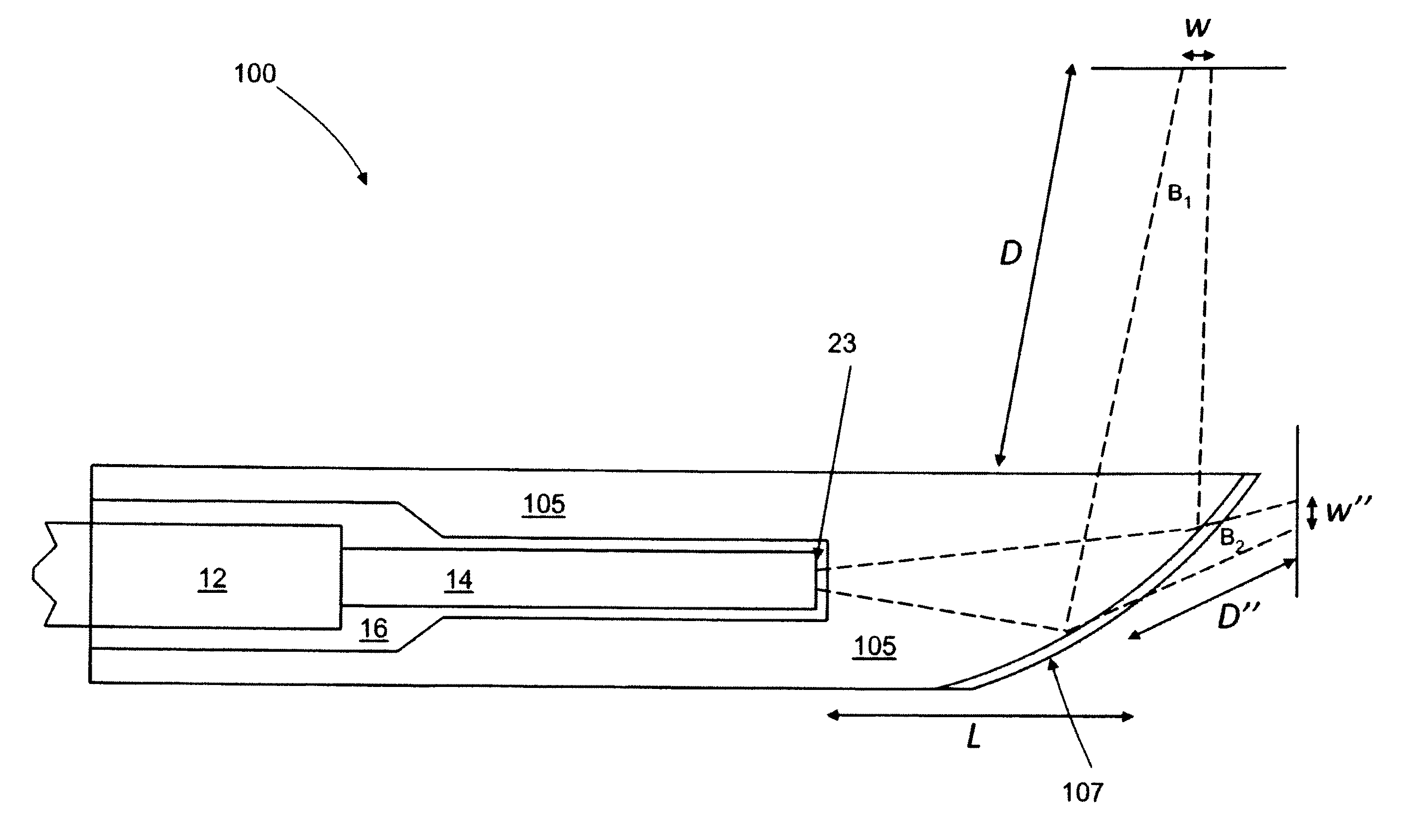
[0109]FIG. 7 shows another system embodiment 100 of the present invention that uses a cap 105, where light radiating from the tip 23 of the fiber is split into two focused beams B1, B2 by a partially-reflecting coating on the distal end face 107 of the miniature optical cap 105. In this embodiment, light radiating from the fiber tip 23 expands into a length L of solid material. The light impinges on the distal end face 107, where it interacts with a partially reflecting coating that transmits a portion of the light through the end face and reflects another portion of the light through the side face of the cap. The reflected portion of the light B1 reaches a focal plane at a first working distance D with a focal spot size w. The transmitted portion of the light B2 reaches a second focal plane at a second working distance D″ with a second focal spot size w″. If the cap is to be placed inside of a sheath, it is understood that the solid length L and the distal end face surface sag can ...


PUM


Abstract

In part, the invention relates to optical caps having at least one lensed surface configured to redirect and focus light outside of the cap. The cap is placed over an optical fiber. Optical radiation travels through the fiber and interacts with the optical surface or optical surfaces of the cap, resulting in a beam that is either focused at a distance outside of the cap or substantially collimated. The optical elements such as the elongate caps described herein can be used with various data collection modalities such optical coherence tomography. In part, the invention relates to a lens assembly that includes a micro-lens; a beam director in optical communication with the micro-lens; and a substantially transparent film or cover. The substantially transparent film is capable of bi-directionally transmitting light, and generating a controlled amount of backscatter. The film can surround a portion of the beam director.

Description

CROSS-REFERENCE TO RELATED APPLICATIONS[0001]This application is a continuation-in-part of U.S. patent application Ser. No. 11 / 983,526, filed Nov. 12, 2007, now U.S. Pat. No. 7,813,609. This application also is a continuation-in-part of International Application No. PCT / US2008 / 012701, filed Nov. 12, 2008. The entire contents of the above-identified applications are incorporated by reference herein.FIELD OF THE INVENTION[0002]This invention relates generally to optical elements, the design and manufacture of optical elements, and methods of using the same. In addition, the invention also relates to using optical elements to collect data with respect to a sample of interest.BACKGROUND OF THE INVENTION[0003]Optical analysis methods such as interferometric methods deliver light onto a sample of interest, and further require collection of a portion of the light returned from the sample. Due to the size and complexity of many light sources and light analysis devices, they are typically lo...

Claims


Application Information

Patent Timeline
Patent Type & Authority Patents(United States)
IPC IPC(8): G02B6/26G01B11/14
CPCA61B5/0066G02B6/262A61B5/0084A61B5/6852G02B23/2423G02B27/0911G02B27/0955G02B27/0977G02B27/0994A61B5/6876G02B6/4214G02B6/4206G02B6/4204A61B1/00137A61B1/005A61B1/07A61B5/02007G01B9/02091A61B5/0071G02B5/08A61B6/504A61B5/0068G02B6/32G02B27/005G02B23/26G02B27/095
Inventor ADLER, DESMONDMCCARTIN, STEPHENPETERSEN, CHRISTOPHERSCHMITT, JOSEPH
Owner LIGHTLAB IMAGING
Learn More