
Wave power generator

a wave power generator and generator technology, applied in the direction of electric generator control, machines/engines, mechanical equipment, etc., can solve the problems of increasing the cost of energy, serious environmental pollution, and future threats, and achieve the effect of high energy conversion efficiency, increased investment efficiency, and encouraging active investment and research

Inactive Publication Date: 2013-12-31
JO CHANG HUI
View PDF17 Cites 9 Cited by
  • Summary
  • Abstract
  • Description
  • Claims
  • Application Information

AI Technical Summary

Benefits of technology

This patent describes a wave power generator that has high efficiency in converting wave energy into electricity. This makes it easier to attract investment and research, as well as improve the practicality and value of the power resource as a clean energy source. Additionally, the patent suggests ways to improve the structure of the generator to further enhance efficiency and stability, as well as control output fluctuations and secure leveling of power output.

Problems solved by technology

Our future is being threatened by exhaustion of fossil fuel resources, increasing cost pressure of energy due to reduced production and cost advancing pressure from oil-producing countries, and serious environmental pollution coming out from energy consumption.
However, nuclear energy even having economic feasibility has been restrictively developed only in some countries due to the Nuclear Nonproliferation Treaty and radioactive contamination, meanwhile water energy and tidal energy require proper site location satisfying system requirements, anticipated excessive investment and long-term construction period, while solar energy and wind energy require storage cell due to intermittent generation and higher cost.
In particular, energy resources from sea wave are out of count.
However, most countries in the world have not yet focused on investment or research on wave power generation, and only small air turbine generators have been introduced installed at marine buoys and at wave bather.
Due to high fluctuation of sea wave (wave period, cycle and height) coming out from varying weather and seasons, technologies of wave power generation had been out of interest in research and investment.
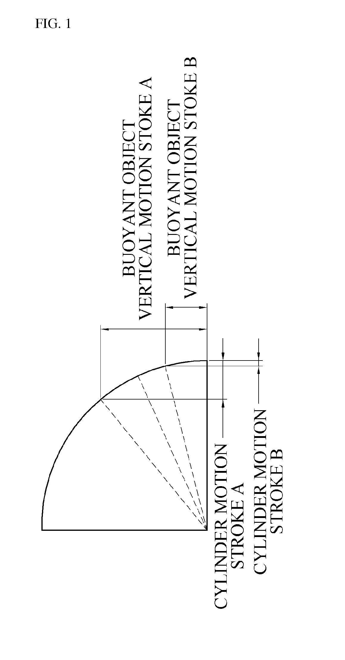
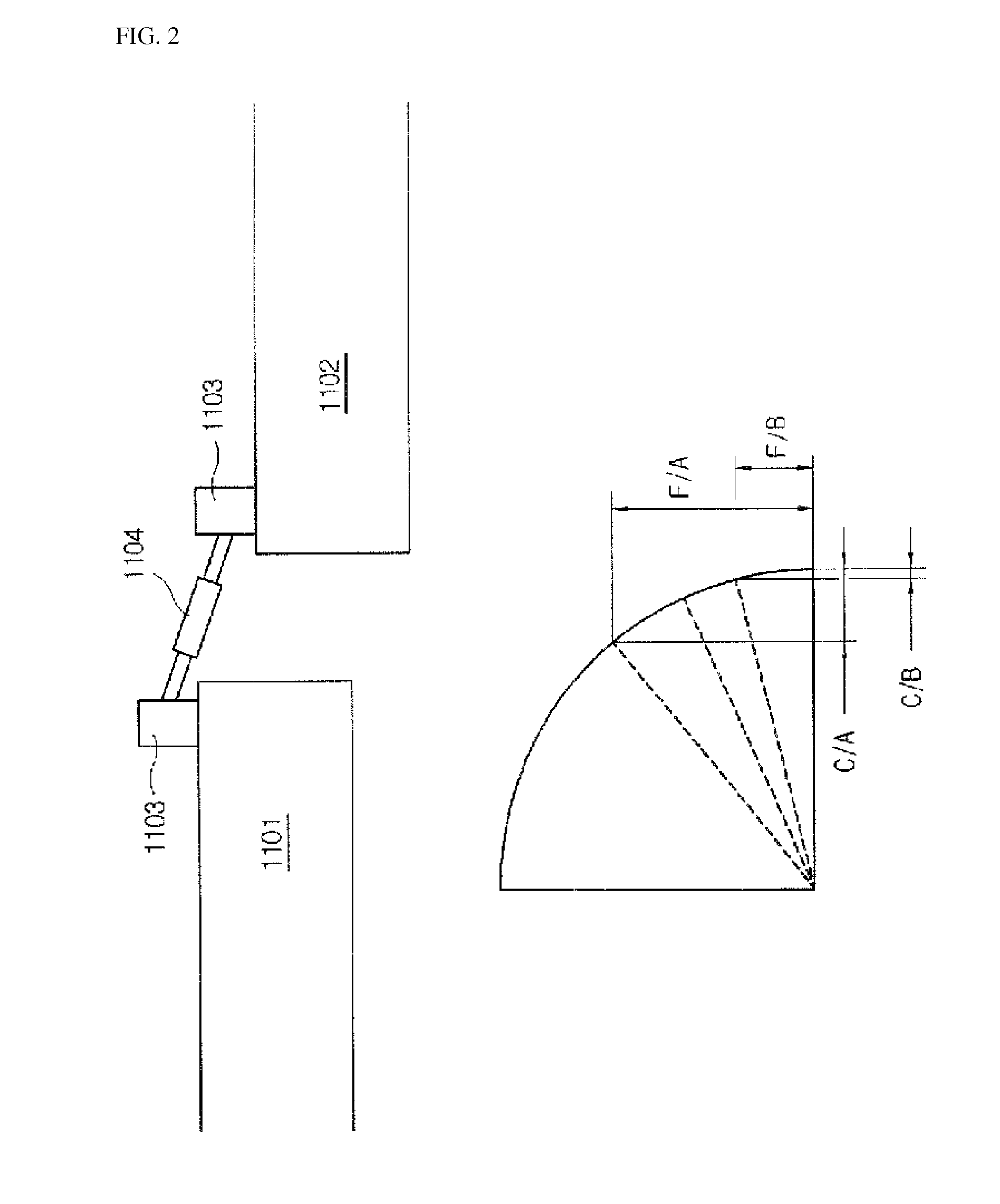
However, the method in which rafts connected each with hydraulic cylinders tied by hinges to convert wave movement into hydraulic pressure from axial movement in cylinder has disadvantages resulting from short motion stroke of the hydraulic cylinder arm and lower conversion efficiency from sharply decreasing cylinder stroke on the lower wave height.
That is, the cylinder motion stroke is abruptly reduced when the wave height is lowered, and thus, the energy conversion efficiency is sharply reduced.
In other words, since energy is in proportion to the square of a velocity, the movement velocity of the cylinder is reduced, and thus, the wave power generator cannot be easily adapted to the waves with a low wave height.
Eventually, various conventional wave power generators in stages of development and practical use have various difficulties such as inactive investment and research caused by fearing low efficiency of energy conversion and uncertainties of natural environment and energy outputs, and impracticability caused by following high investment and low return, and thus, supplements thereof are needed.
That is, the cylinder motion stroke is abruptly reduced when the wave height is lowered, and thus, the energy conversion efficiency is sharply reduced.
In other words, since energy is in proportion to the square of a velocity, the movement velocity of the cylinder arm is reduced, and thus, the wave power generator cannot be easily adapted to the waves at low wave height.
Ultimately, in coastal environments in which the wave height W / H is small, a simple system as shown in FIGS. 2 and 3 cannot be easily adapted.

Method used


Image

  • Wave power generator
  • Wave power generator
  • Wave power generator

Examples


Embodiment Construction

[0044]Hereinafter, exemplary embodiments of the present invention will be described in detail with reference to the accompanying drawings.

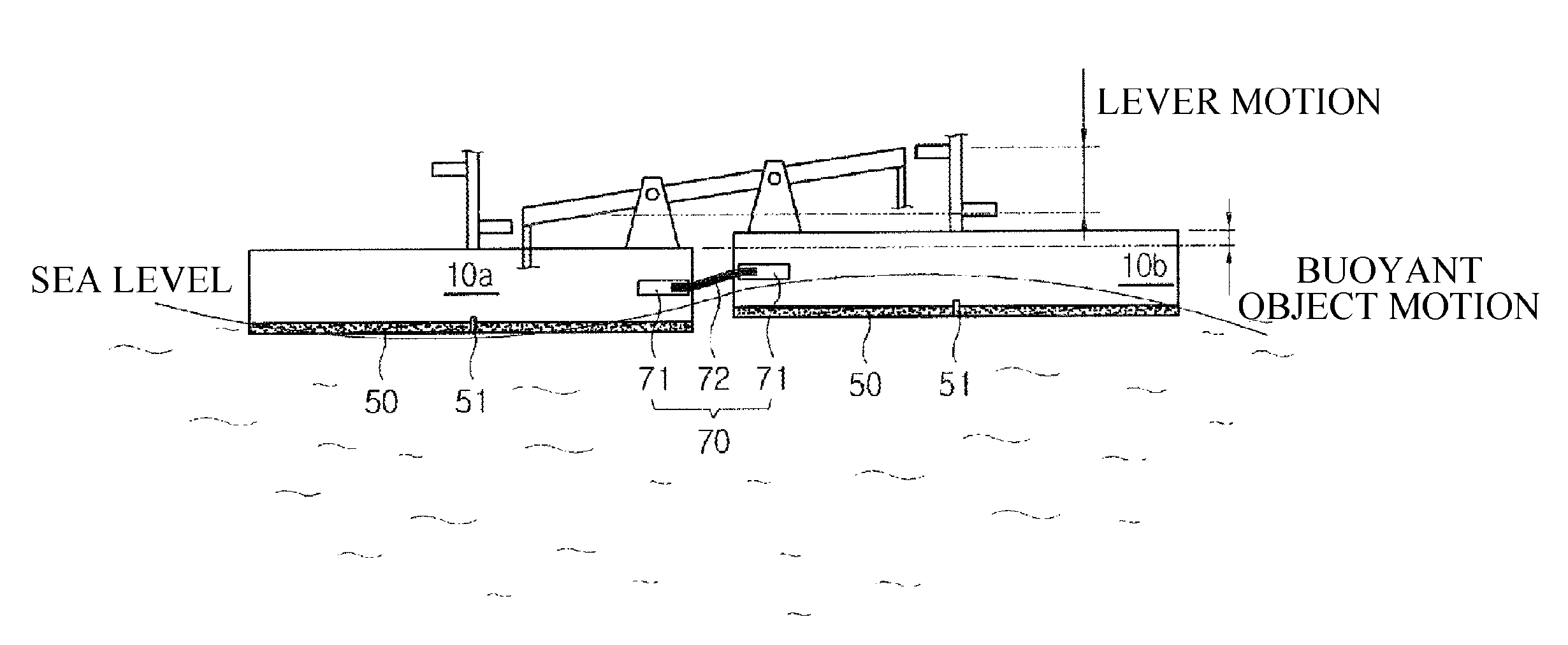
[0045]FIG. 4 is an explanatory view of the principle of leverage, and FIG. 5 is a schematic structural view showing a wave power generator according to an exemplary embodiment of the present invention. FIG. 6 is an explanatory view of partial motion of FIG. 5, and FIG. 7 is an enlarged view of region B of FIG. 5. FIG. 8 is a front structural view of FIG. 7. FIG. 9A and FIG. 9B each show the operation of FIG. 8. FIG. 10 is a flowchart of the wave power generator according to the exemplary embodiment of the present invention, and FIG. 11 is a plan view of an installation structure of the wave power generator according to an exemplary embodiment of the present invention.

[0046]Referring to the figures, mainly FIGS. 5 and 6, the wave power generator of the present embodiment includes a plurality of rafts 10a and 10b that are disposed on a surface of wa...


PUM


Abstract

The present invention relates to a wave power generator, and more particularly, to a wave power generator that has comparatively high energy conversion efficiency, so that it can induce active investment and research and development to overcome uncertainties about the natural environment, and which can enhance practicability and value as a clean energy source, especially by virtue of the improved return on investment thereof. For this purpose, the wave power generator of the present invention is characterized in that is comprises: a plurality of rafts arranged on a water surface to move freely with the movement of waves; a plurality of connectors, connecting the plurality of rafts to each other, for performing the conversion of kinetic energy by converting the wave-induced movement of one raft into an amplified lever movement on an adjacent raft; a plurality of generators installed on the plurality of rafts to generate electricity; and an energy-converting unit, connected to the plurality of connectors and to the plurality of generators, for converting the kinetic energy from the plurality of connectors into rotational energy for driving the plurality of generators.

Description

TECHNICAL FIELD[0001]Considering the present invention of clean energy generation from wave power, for encouraging active investment and research activities to the wave power generator, power generation system is to have relatively high conversion efficiency from wave energy and complementing irregular output from uncertainty of environment by nature, and to enhance practice and value as a clean energy resources, especially by virtue of the improved return on investment thereof.BACKGROUND ART[0002]Our future is being threatened by exhaustion of fossil fuel resources, increasing cost pressure of energy due to reduced production and cost advancing pressure from oil-producing countries, and serious environmental pollution coming out from energy consumption.[0003]In addition, conventional power generation system using fossil fuels, there are various power generation systems using various kinds of energy resources such as nuclear energy, tidal energy, water energy, wind energy, solar ene...

Claims


Application Information

Patent Timeline
Patent Type & Authority Patents(United States)
IPC IPC(8): F03B13/10
CPCY02E10/38F05B2260/406F05B2260/4031F03B13/20Y02E10/30Y02E10/20F03B13/14F03B17/02
Inventor JO, CHANG-HUI
Owner JO CHANG HUI
Learn More