Thermally assisted magnetic recording disk with ion-implant facilitated non-magnetic regions, manufacturing method thereof, and magnetic recording method

a technology of magnetic recording disk and ion-implant, which is applied in the field of magnetic recording disk, can solve the problems of limiting the recording magnetic field of the head, increasing the tpi, and restricting the cross-talk from occurring, so as to improve the accuracy of information reading and record high contrast.

Active Publication Date: 2014-01-21
WESTERN DIGITAL TECH INC
View PDF7 Cites 74 Cited by
  • Summary
  • Abstract
  • Description
  • Claims
  • Application Information

AI Technical Summary

Benefits of technology

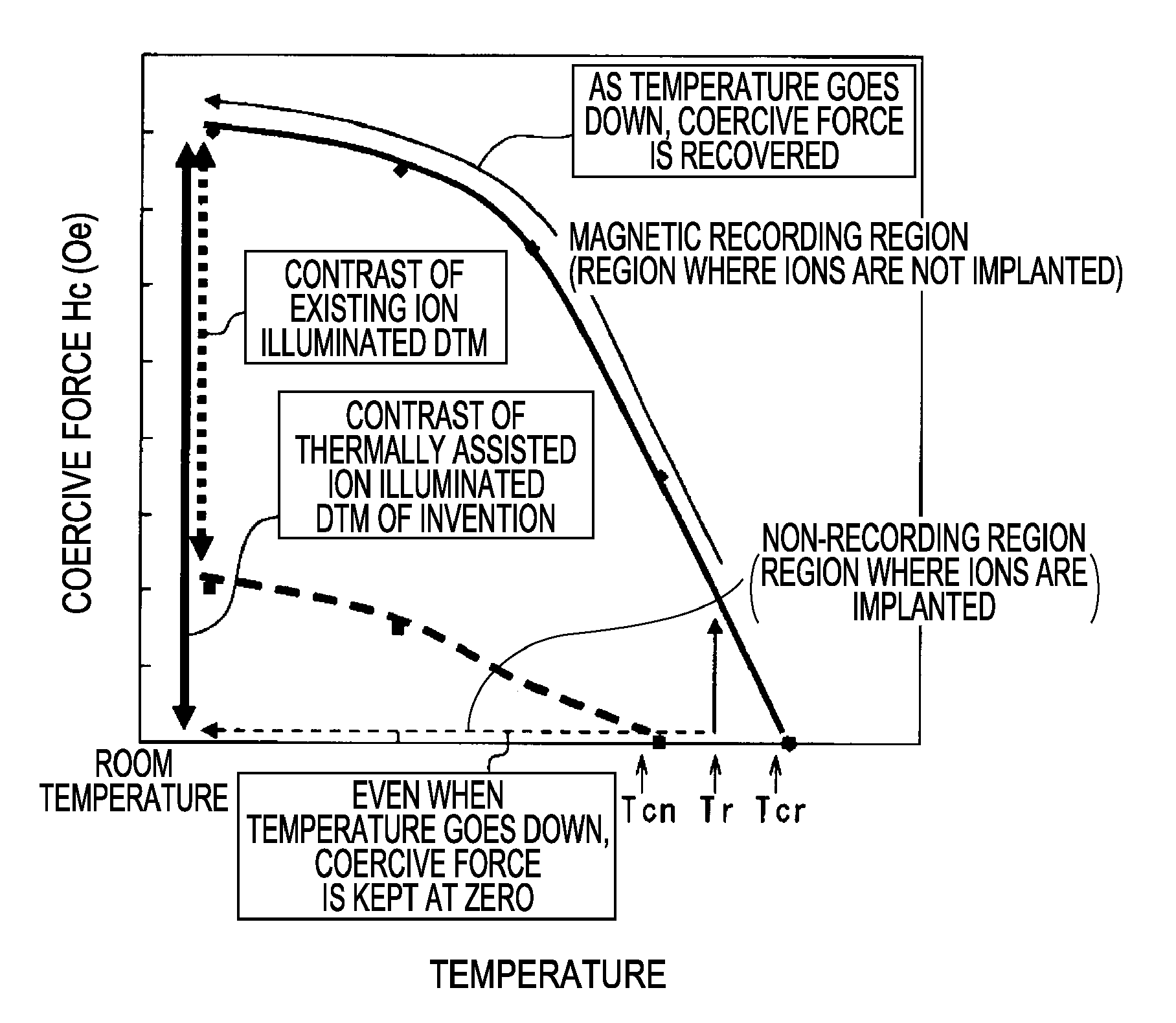
[0041]In the magnetic recording disk such as DTM according to the invention, among the magnetic recording layer thereof, only the non-recording region that magnetically separates the magnetic recording region is made low in Hc by an ion implantation method (also called an ion illuminating method), and only a portion necessary in information recording is heated by a thermally assisted magnetic recording method to magnetically record the information. The principle thereof will be described. In the invention, according to the ion implantation method, the Hc only needs to be lowered to an extent by which an effect of the invention can be obtained. That is, only semi-hard magnetization, soft magnetization or weak magnetization needs to be applied.
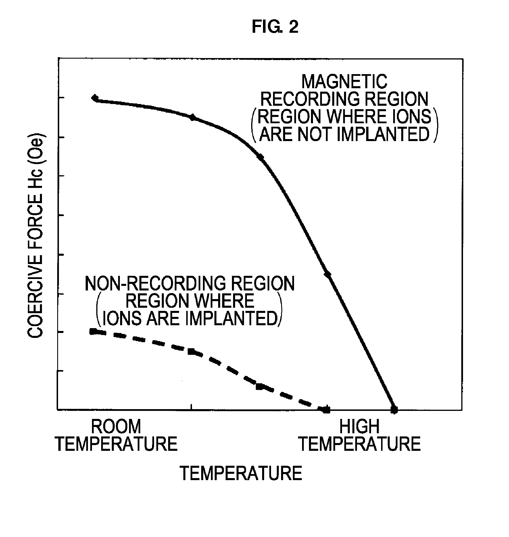
[0042]In general, a value of the coercive force (Hc) of a magnetic material that exhibits ferromagnetism decreases as the temperature goes up (FIG. 2). Furthermore, in the ion-implanted portion (non-recording region), the coercive force becomes smaller in comparison with the portion that is not ion-implanted (magnetic recording region) (FIG. 2).
[0043]As the result thereof, when compared based on a temperature (Curie temperature) where the coercive force (Hc) becomes zero, the Curie temperature (Tcn) of an ion-implanted portion becomes lower than the Curie temperature (Tcr) of a portion where ions are not implanted (FIG. 2).
[0044]The invention makes use of the phenomenon, and, to a magnetic disk having the above-mentioned structure, a temperature during magnetic recording (Tr) is set to a temperature between the Curie temperatures of these regions.
[0045]When the temperature is set in the region, although the portion where ions are not implanted (magnetic recording region) is ferromagnetic, the portion where ions are implanted (non-recording region) exhibits paramagnetism. Accordingly, the non-recording region, even when a magnetic field is applied with a magnetic recording head, can not be recorded since there is no residual magnetization because of paramagnetism. Accordingly, even when a temperature decreases, the magnetization is maintained at zero (FIG. 3).
[0046]On the other hand, the magnetic recording region is ferromagnetic even at the temperature (Tr) during magnetic recording; accordingly, when a magnetic field of the magnetic recording head is applied, the magnetic recording region is magnetized in a direction of the recording magnetic field to generate residual magnetization. Then, as the temperature goes down, the coercive force is recovered to be large (FIG. 3). As the result thereof, in the magnetic recording region, recording signals remain strong, and the recording signal does not at all remain in an adjacent non-recording region. Accordingly, a magnetic contrast between both regions becomes strong, remarkably improving accuracy during information reading.

Problems solved by technology

However, when a material that is more than ever high in the coercive force and large in magnetic anisotropy is used in a magnetic recording portion, there occurs a problem of a limit of a recording magnetic field of the head.
However, owing to the heat distribution, the magnetic body becomes instable to cause a problem that, during writing-in of information, a so-called cross-talk phenomenon where information of an adjacent track that is not wanted to record is rewritten occurs to inhibit increasing of the TPI.
However, according to the method, there is no physical countermeasure to a boundary region with an adjacent track; accordingly, there is a limit in inhibiting the cross-talk from occurring and a requirement for high densification cannot be met.
There is a further disadvantage that a magnetic disk structure is complicated to increase a manufacturing cost.
However, in order to bury the non-magnetic material in the non-recording portion, a complicated process has to be undergone; accordingly, there is a problem from the economical point of view.

Method used


Image

  • Thermally assisted magnetic recording disk with ion-implant facilitated non-magnetic regions, manufacturing method thereof, and magnetic recording method
  • Thermally assisted magnetic recording disk with ion-implant facilitated non-magnetic regions, manufacturing method thereof, and magnetic recording method
  • Thermally assisted magnetic recording disk with ion-implant facilitated non-magnetic regions, manufacturing method thereof, and magnetic recording method

Examples


examples

[0081]A nonmagnetic and heat-resistant disk-like glass substrate having a diameter of 65 mm was prepared, and, on the glass substrate, 80Fe-8Ta-12C (100 nm) as a soft magnetic layer, then MgO (20 nm), Fe (1 nm) and Au (40 nm) as an intermediate layer were sputter deposited at room temperature.

[0082]Then, the substrate was heated to 300° C., followed by sputter-depositing FePt (15 nm) thereon, further followed by annealing at 500° C. to form an ordered alloy. It was confirmed with X-ray that FePt is formed into an ordered alloy. In FIG. 5A, layers upper than the FePt layer 4 are illustrated.

[0083]Furthermore, a carbon film (not shown in the drawing) made of diamond-like carbon was deposited at a thickness of 3 nm according to a CVD method, and thereon a room temperature nano-imprint resist (SOG) was coated to form the resist mask layer 6. A thickness of the resist mask layer was set to 80 nm (FIG. 5A).

[0084]The patterning was conducted according to a nano-imprint method, a pitch of a...


PUM

PropertyMeasurementUnit
temperatureaaaaaaaaaa
coercive forceaaaaaaaaaa
temperatureaaaaaaaaaa

Abstract

The invention provides a magnetic disk that solves (1) a problem of cross-talk that cannot be solved even by an existing thermally assisted recording method or a discrete method (DTM or the like), (2) a problem of surface flatness, which an existing embedding type DTM or the like has, and (3) a problem of a difference in thermal expansion coefficient between materials when a thermally assisted method is applied to the DTM, and that (4) does not necessitate a special medium structure, and is excellent in a surface flatness and economically and functionally high in realizability. A DTM manufactured by ion implantation is excellent in the surface flatness, and can solve the cross-talk problem by conducting the thermally assisted recording at a temperature between a Curie temperature (Tcn) of a portion where ions are implanted (non-recording region) and a Curie temperature (Tcr) of a portion where ions are not implanted (recording region).

Description

BACKGROUND[0001]1. Field of the Invention[0002]The present invention relates to a magnetic disk that utilizes a thermally assisted method during magnetic recording in a magnetic recording apparatus.[0003]2. Description of the Related Art[0004]As a digital information technology develops, high capacity of a recording apparatus and miniaturization and light weight of an apparatus are in demand. In order to respond to the demand, in a magnetic recording apparatus, in particular, a magnetic disk recording apparatus (for example, Hard Disk Drive (HDD)), a high recording density is being pursued. In recent years, developments and researches for achieving a surface recording density of 1 Tb / in2 or more are under way.[0005]The high recording densification of a magnetic disk recording apparatus has been realized by miniaturizing a dimension of a recording bit. However, as the recording bit is miniaturized, there occurs a problem that a thermal fluctuation phenomenon where the magnetization i...

Claims


Application Information

Patent Timeline
Patent Type & Authority Patents(United States)
IPC IPC(8): G11B5/02G11B5/716G11B5/82
CPCB82Y10/00G11B5/743G11B5/855G11B5/82
Inventor YASUMORI, JUNICHISONOBE, YOSHIAKI
Owner WESTERN DIGITAL TECH INC
Why Eureka
Try Eureka