One problem associated with the kind of propulsion system described above is that the complete system occupies more space than ordinary propulsion systems such as an ordinary vehicle only having an ICE or a purely
electric vehicle.
The purely electric driven vehicle is not in general able to travel as long distances as an ordinary ICE driven vehicle due to limits of the maximum
stored energy and the
electric motor is usually not as strong as the ICE with slower accelerations and worse performance when a large torque is required, e.g. when starting and driving a heavy loaded vehicle, in steep uphills or when a fast acceleration is desired, for example at
overtaking.
However, the above described systems are rather complicated and it is a general desire when designing a
hybrid drive train system and control features thereof to provide a compact system in order to avoid an unnecessary bulky and heavy construction.
However, one possible problem with such a compact system may be to manage to control the drive train system with a desired accuracy.
There is an almost constant need to generate electrical energy and store it in a battery or the like
energy storage device since the capacity of the battery generally is rather limited.
a) Setting the drive train system in a generating mode when the vehicle is at standstill with its ICE running and there is a
signal indicating that electric generation is desired. An indication of desired energy generation may for example be the
State Of Charge (SOC) of the battery, an indicator of time at standstill conditions or a manually triggered
signal indicating that
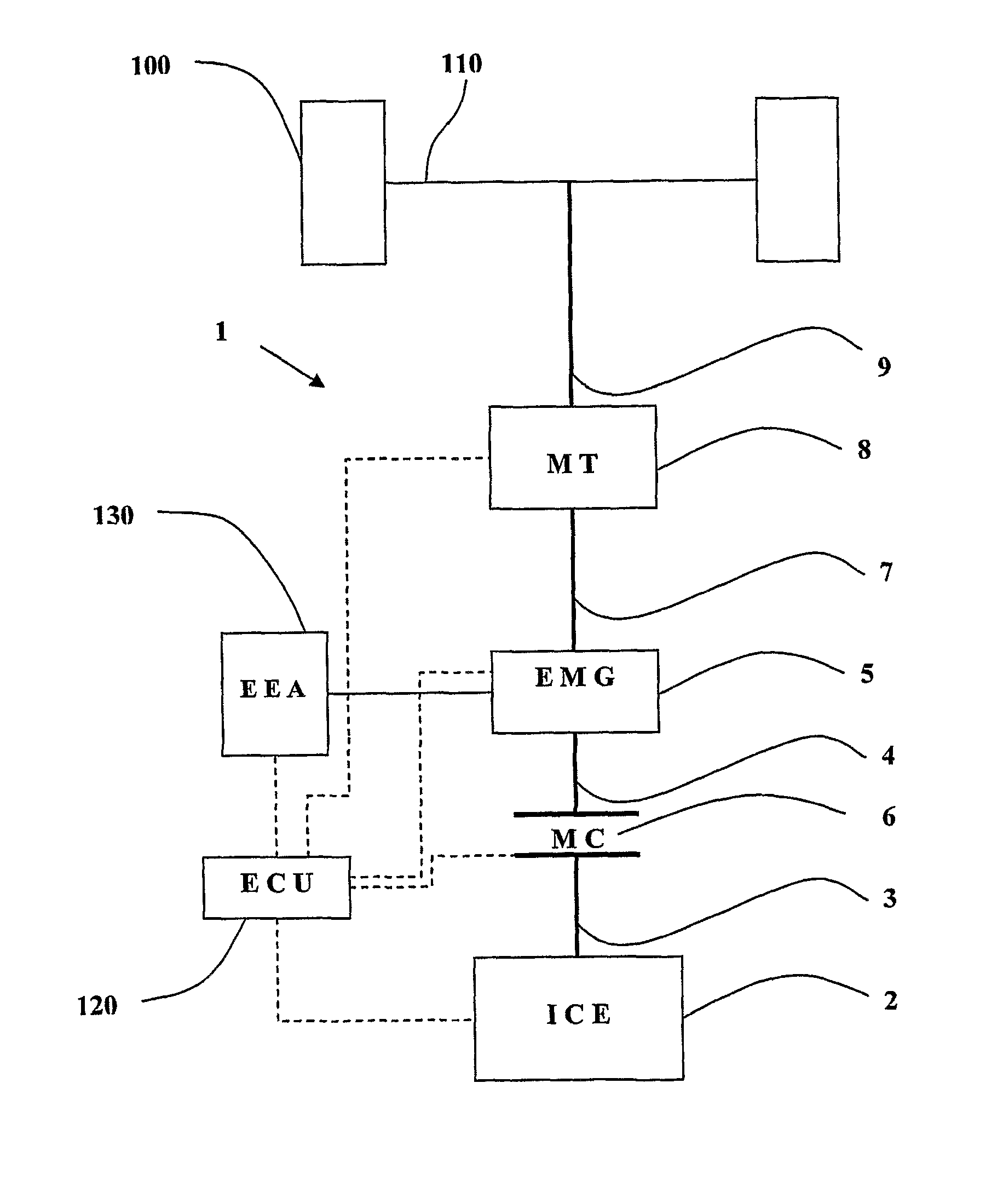
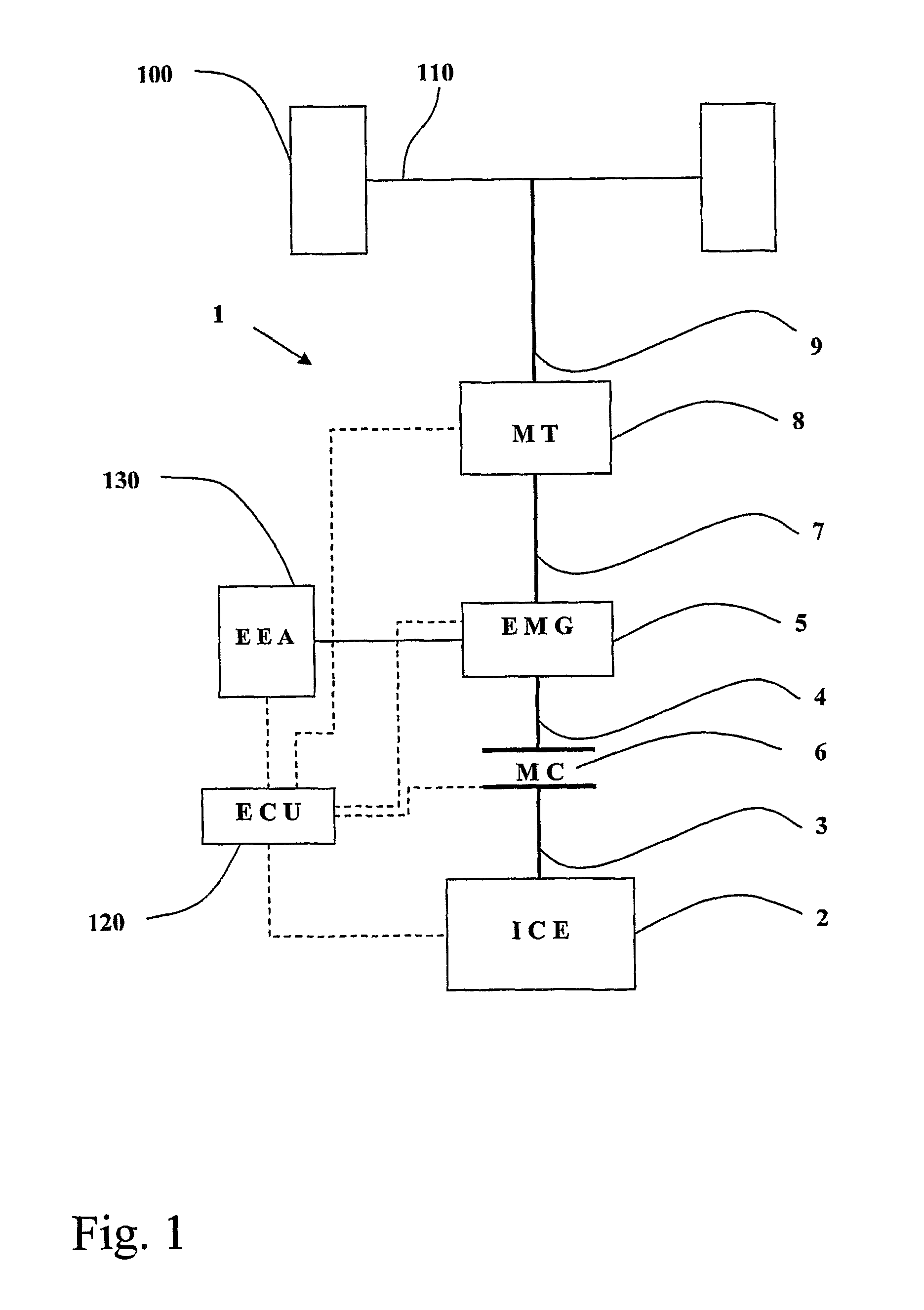
electricity generation is desired. This standstill or idle generating mode includes the features of setting the MC to be engaged such that the EMG is rotating in a generating mode and the end actuators are decoupled by the use of a synchronized gear of the
mechanical transmission set in neutral mode. The ICE and EMG are preferably controlled such that the ICE is working in an optimal manner concerning such aspects as (fuel) efficiency and low concentrations of noxious components in the exhaust gases while the rotational speed of the EMG preferably is optimised concerning an efficient generation of
electricity. This is usually achieved by controlling the rpm of the ICE and the load on the EMG. Even though it would be possible to incorporate some kind of gear or transmission arrangement between the output shaft of the ICE and the input shaft of the EMG, in order to set the rotational speed of the input shaft for optimal generation of electricity at the desired idling speed of the ICE at regeneration, the
gear ratio between the output shaft of the ICE and the input shaft of the EMG is usually 1:1, e.g. by using a positive engaging
clutch such as a
dog clutch, in order to avoid friction losses while keeping the system compact and simple.
b) Starting the change of mode from idle to driving as a response to an input
signal to the ECU indicating that a motion of the vehicle is desired. This signal may for example be triggered by a gear change from neutral to forward or rear, pressing down of the accelerator pedal or release of a service
brake /
parking brake or any other suitable indication of a status or change of status of a relevant parameter.
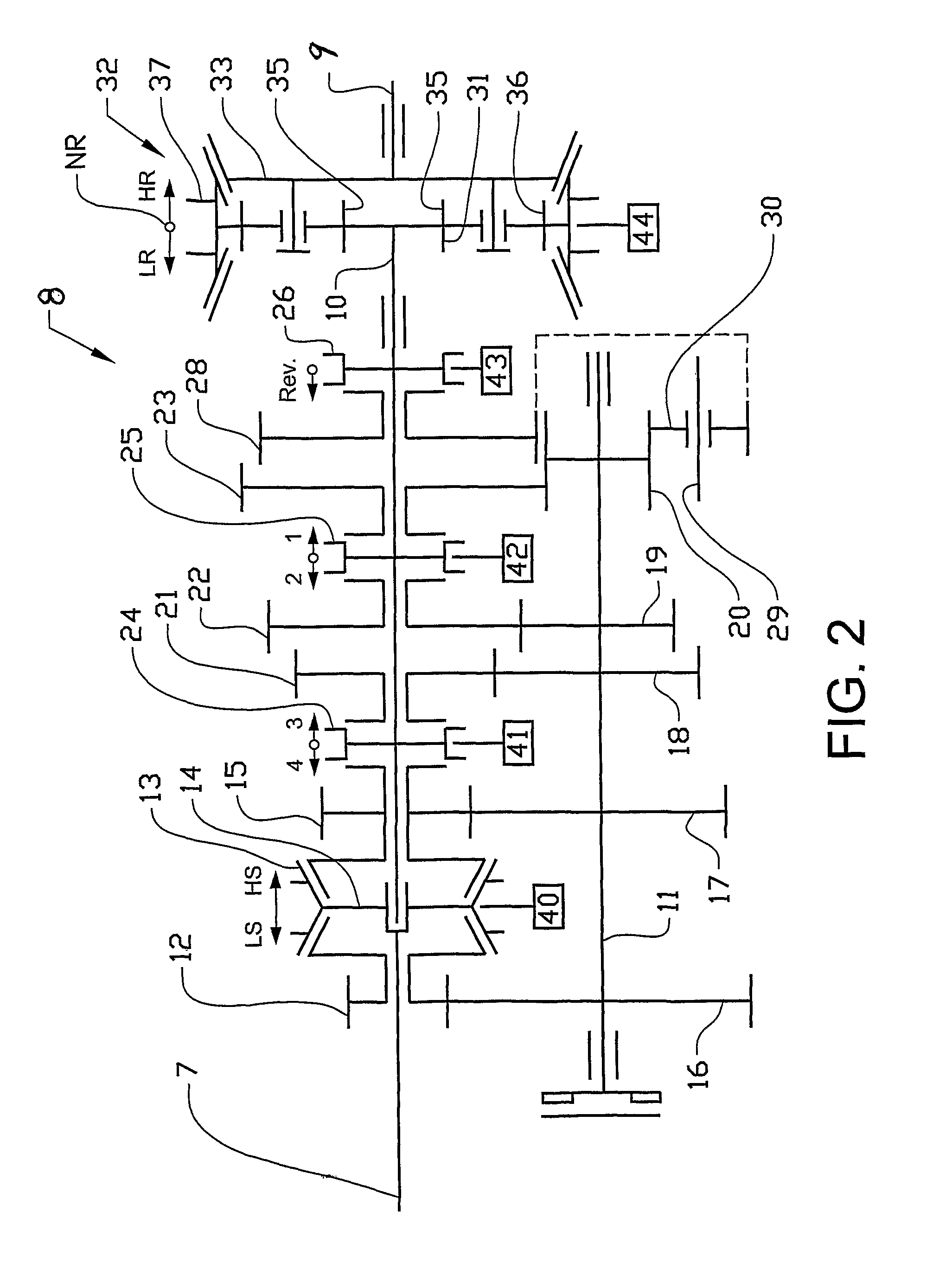
c) Disengage the MC such that the ICE and EMG are disengaged from each other. By disengaging the ICE from the EMG, the rotational speed of the EMG may be decreased rather quickly. Furthermore, the synchronization arrangement of the above mentioned synchronized gear, which was used to decouple the end
actuator (e.g., vehicle wheels) from the EMG and ICE, is engaged. By engaging the synchronization arrangement of the gear, which earlier was set in neutral mode, it will be possible to transmit a torque to the end actuators from for example the inertial forces while retarding the rotational speed of the EMG. An advantageous feature by using this control method is that there will be a faster response of the
start up of the vehicle in response to a signal indicating that a motion of the vehicle is desired. As described in the control method in US 2007 / 0095584, there is a
waiting time from the point of time it is indicated that a change from a generative, still standing mode to moving of the vehicle is desired due to the waiting for the slow down of the EMG to zero or close to zero before the gear is shifted from neutral to a selected gear. This
waiting time may be annoying for the driver who is used to feel a response directly to his control actions. Hence, the present control method will make the vehicle start to move more quickly as a response to an appropriate input signal indicating a motion of the vehicle is desired. Hence the synchronization procedure and the synchronized gear will be used in order to transmit a torque from the EMG, (preferably via inertial forces of the EMG and associated shafts), to the end actuators, e.g. wheels in the case of an ordinary car,
truck or
bus. In addition to be able to use the energy stored as
inertia forces in the system to provide an immediate response to the desire to move, it will also have the benefit of using
mechanical energy directly without the need of converting it to electrical energy before it is reconverted to
mechanical energy or, still worse,
brake the rotation of the EMG by the use of a friction
brake or the like device such that the inertial energy is lost as friction. The overall energy efficiency may thus be improved by the use of the control strategy herein described. Still another
advantage is that the retardation of the rotational speed of the EMG while setting the vehicle in motion by the use of the synchronization arrangement will also contribute to a smooth start of the vehicle. Hence, the EMG will retard due to the braking force of the synchronization of the
mechanical transmission and at least a part of the inertial energy of the EMG will be transferred to the end actuators and the vehicle will smoothly start to move.
d) When the EMG has slowed down enough such that the rotational speed is within the
speed limit to engage the positive
coupling of the synchronized gear, the EMG and the end actuators will be connected by the positive
coupling of the synchronized gear. Hence, the EMG may now start to work as a motor and be the power source of the vehicle during start and acceleration of the vehicle.
On the other hand, the fork pressure in the synchronization arrangement should not be too high to avoid a jerky or abrupt start which may be inconvenient for drivers or passengers and such an abrupt start may also cause wear of the drive train system due to large reaction forces when starting.
