
Catalyst for purifying exhaust gas from internal combustion engine and process for purifying exhaust gas using the same

a technology of catalyst and exhaust gas, which is applied in the direction of metal/metal-oxide/metal-hydroxide catalyst, machine/engine, etc., can solve the problems of large amount of reducing hydrocarbon supplied to fuel, difficulty in combustion of hydrocarbon, and small amount of oxygen required for burning hydrocarbon. , to achieve the effect of high combustion activity

Active Publication Date: 2014-07-08
UMICORE SHOKUBAI USA +1
View PDF39 Cites 7 Cited by
  • Summary
  • Abstract
  • Description
  • Claims
  • Application Information

AI Technical Summary

Benefits of technology

The present invention is a catalyst that can purify exhaust gas from an internal combustion engine. It is designed to increase the level of palladium in a catalyst and to support it in an oxidation state where it is more effective in removing hydrocarbon from exhaust gas. This enables the catalyst to have high combustion activity even at a low air-fuel ratio, such as during engine acceleration. The catalyst is able to reduce the amount of palladium in its highest oxidation state (4-valence) and increase the amount in a lower state (2-valence) which is more favorable for hydrocarbon removal. This is achieved by using a specific method to oxidize the palladium surface, which results in a high level of surface oxidation state where 2-valence and / or 4-valence is dominant over 0-valence.

Problems solved by technology

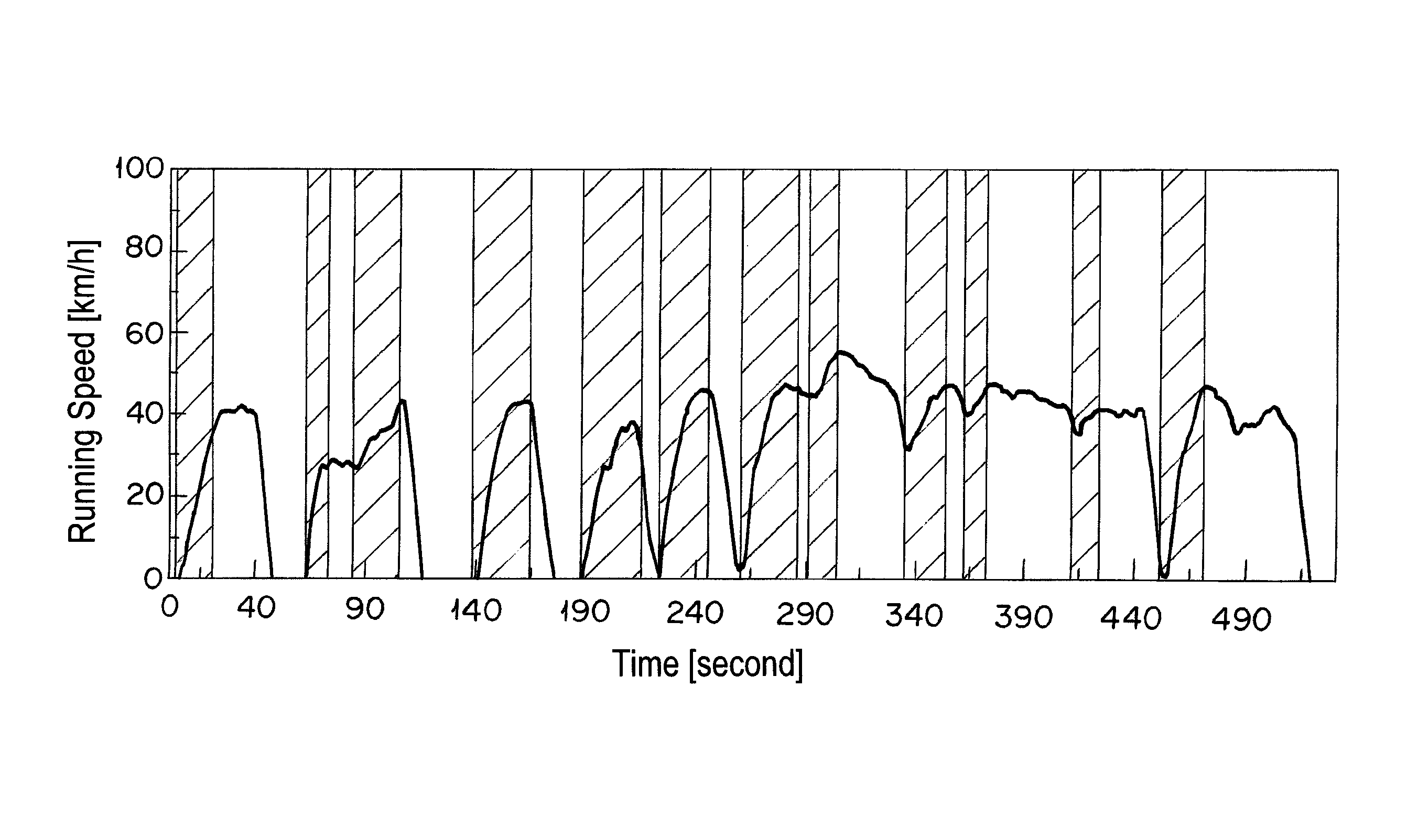
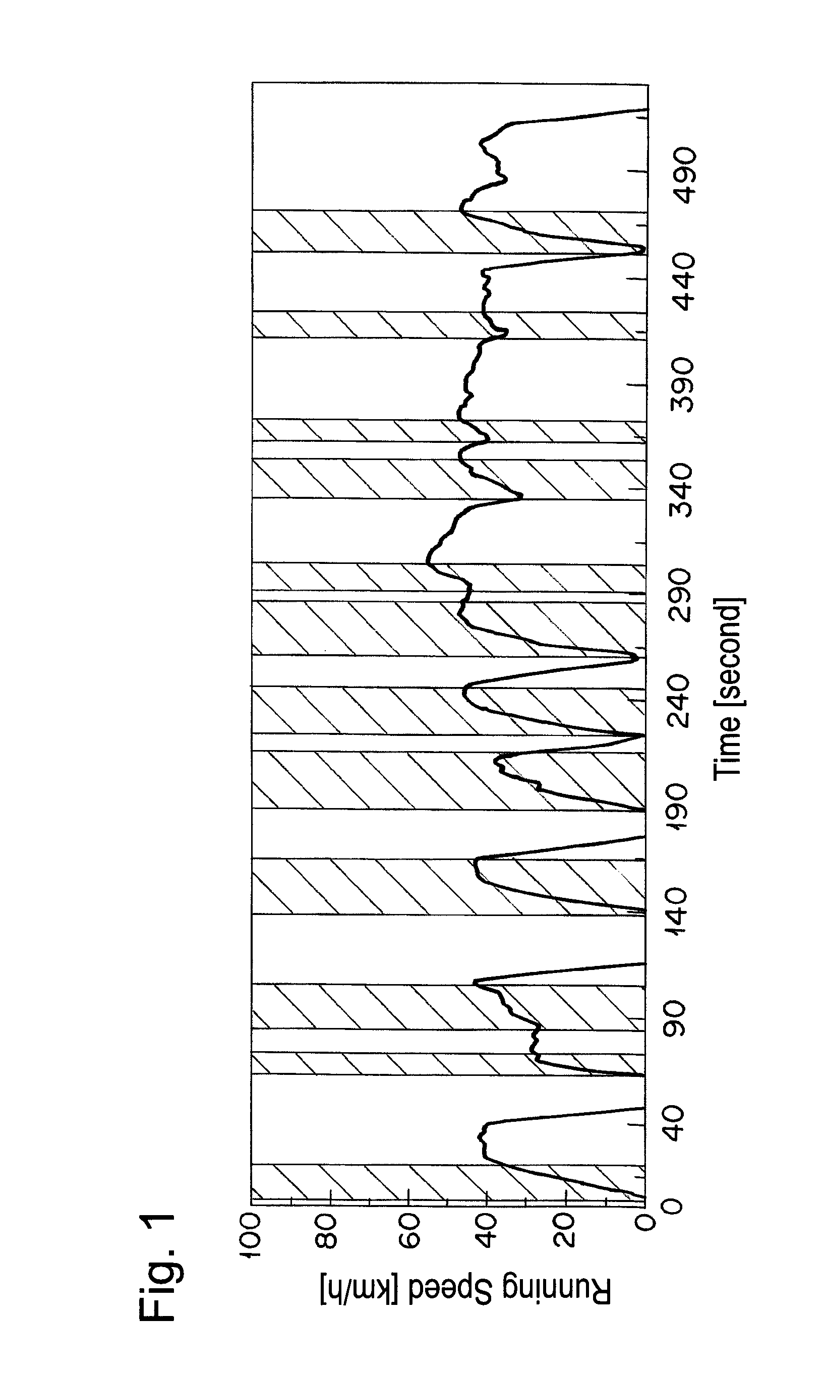
In engine acceleration period, a space velocity increases and the contact time between a catalyst and an exhaust gas becomes shorter, which makes combustion of hydrocarbon difficult.
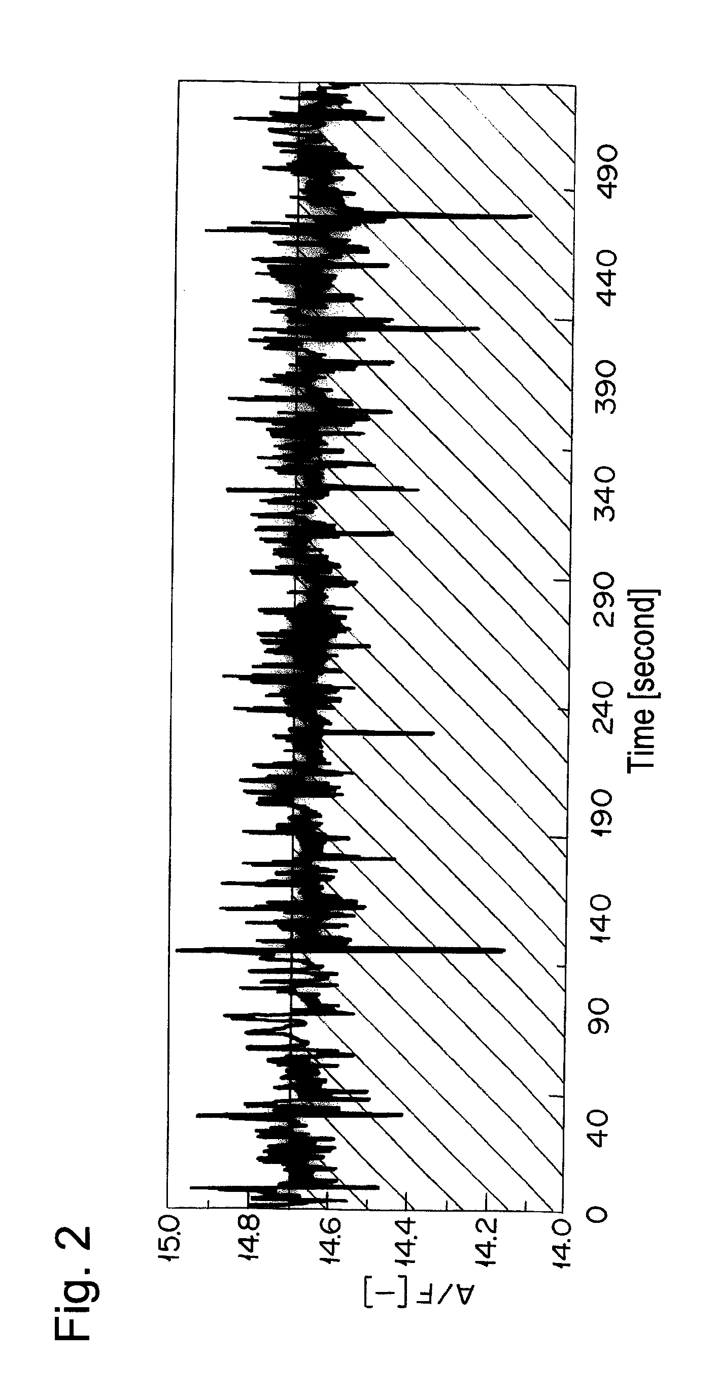
Specifically, a fuel containing a large amount of reducing hydrocarbon is supplied excessively, while amount of oxygen required for burning the hydrocarbon is small.
However, none of the methods described in JP-A-11-013462, JP-A-2004-114014, and U.S. Pat. No. 5,884,473 describes a surface oxidation state or surface palladium valence.
Although U.S. Pat. No. 5,958,828 describes a sintering phenomenon due to reduction of palladium oxide (PdO), it does not disclose a concrete value indicating an oxidation state of palladium.

Method used


Image

  • Catalyst for purifying exhaust gas from internal combustion engine and process for purifying exhaust gas using the same
  • Catalyst for purifying exhaust gas from internal combustion engine and process for purifying exhaust gas using the same
  • Catalyst for purifying exhaust gas from internal combustion engine and process for purifying exhaust gas using the same

Examples


example 1

[0062]Using palladium nitrate as a source material for palladium and magnesium oxide as a source material for magnesium, respectively, an aqueous mixed solution of palladium (in terms of palladium), magnesium (in terms of magnesium oxide) and alumina in a weight ratio of palladium:magnesium oxide:alumina=1.25:50:30 was prepared, and wet-milled in a ball mill, to yield a slurry. Then, the slurry was coated on a cordierite with a diameter of 24 mm, a length of 47 mm, and a volume of 0.021 L, dried at 200° C. for 5 min, and calcined at 500° C. for 1 hour in air, to yield a catalyst A having 81.25 g of catalyst active components supported per 1 L of cordierite. As reduced to palladium oxide (PdO), the composition of the catalyst A is as follows: palladium oxide (PdO):magnesium oxide (MgO):alumina=1.44:50:30 (weight ratio).

[0063]The catalyst A was tested for the proportion of palladium having each surface charge by X-ray photoelectron spectroscopy (XPS). The results are shown in Table 1....

example 2

[0068]The catalyst A prepared in Example 1 was calcined at 950° C. for 50 hours in air and filled in a reaction tube. A simulation gas consisted of 200 ppm of NO, 4.7% of CO, 2% of O2, 880 vol-ppm of C3H8 (in terms of methane), 3520 vol-ppm of C3H6 (in terms of methane), 6% by volume of CO2, 7% by volume of H2O, and the balance of nitrogen was supplied thereto at a space velocity (S.V.) of 94,000 h−1. An A / F value was 13.3. The A / F value was calculated according to the formula described in SAE PAPER 650507. Then, only C3H8 and C3H6 were excluded from the simulation gas, and the rest of the gas was supplied to the catalyst A. Thereafter, the reaction tube was heated so as to give the temperature at the catalyst inlet of 260° C. When the temperature of the catalyst inlet was stabilized at 260° C., 880 vol-ppm of C3H8 (in terms of methane) and 3520 vol-ppm of C3H6 (in terms of methane) were supplied to the catalyst A. After 10 min from the start of gas supply, the concentration of hydr...

example 3

[0072]Using palladium nitrate as a source material for palladium and magnesium hydroxide as a source material for magnesium, an aqueous mixed solution of palladium (in terms of palladium oxide (PdO)), magnesium (in terms of magnesium oxide (MgO)) and alumina in a weight ratio of palladium oxide:magnesium oxide:alumina=5.06:20:80 was prepared, and wet-milled in a ball mill, to yield a slurry. As reduced to palladium oxide (Pd), the composition of the catalyst A is as follows: palladium (Pd):magnesium oxide (MgO):alumina=4.4:20:80 (weight ratio). Then, the slurry was coated on a cordierite with a diameter of 24 mm, a length of 47 mm, and a volume of 0.021 L, dried at 200° C. for 5 min, and calcined at 500° C. for 1 hour in air, to yield a catalyst C having 105.06 g of catalyst active components supported per 1 L of cordierite. The catalyst C was tested for the proportion of palladium having each surface charge by a similar method as in Example 1, to find that a higher proportion of pa...


PUM

PropertyMeasurementUnit
speedaaaaaaaaaa
particle sizeaaaaaaaaaa

Abstract

An Object of the patent is to remove highly reducing hydrocarbon exhausted during acceleration period, and to remove efficiently hydrocarbon even after contacting with highly reducing hydrocarbon. By using a catalyst having a higher proportion of palladium having surface charge of 2-valence or 4-valence supported than that of 0-valence by supporting palladium together with magnesium oxide, hydrocarbon exhausted from an internal combustion engine especially during acceleration period can be efficiently removed.

Description

CROSS REFERENCE TO RELATED APPLICATIONS[0001]This application is a National Stage of International Application No. PCT / JP2009 / 054917, filed on Mar. 13, 2009, which claims the priority of Japanese Application No. 2008-071867 filed Mar. 19, 2008. The contents of the prior applications mentioned above are incorporated herein by reference in its entirety.TECHNICAL FIELD[0002]The present invention relates to a catalyst for purifying an exhaust gas from an internal combustion engine and a process for purifying an exhaust gas using the catalyst. More particularly, it relates to a catalyst having excellent performance of purifying hydrocarbon / hydrocarbons (hereinafter referred to as “HC”) contained in a highly reductive exhaust gas such as that exhausted from an internal combustion engine such as a gasoline engine especially at acceleration period, and a purifying process using the catalyst.RELATED ART[0003]As a means for removing hydrocarbon contained in a low-temperature exhaust gas when ...

Claims


Application Information

Patent Timeline
Patent Type & Authority Patents(United States)
IPC IPC(8): B01D53/56B01D53/94B01J8/02B01J20/00B01J21/00B01J21/04B01J23/00B01J23/02B01J23/06B01J23/08B01J23/10B01J23/40B01J23/42B01J23/44B01J23/58B01J23/63B01J29/06B01J29/18B01J37/00B01J37/02C01B21/00C01B23/00C01B25/00C01B31/00C01B33/00C01B35/00C01G28/00C01G30/00F01N3/28
CPCB01J23/58B01D53/944B01D2255/1023B01D2255/1025B01D2255/2047B01D2255/407B01D2258/014B01J23/44B01J23/63B01J37/0036B01J37/0215F01N3/28
Inventor IKEDA, MASANORIGOTO, HIDEKIMIKITA, KOSUKE
Owner UMICORE SHOKUBAI USA
Learn More