Method for improving productivity and process stability in styrene manufacturing system having multiple reactors connected in series

a technology of styrene manufacturing system and reactor, which is applied in the direction of hydrocarbon by hydrocarbon cracking, chemistry apparatus and processes, organic chemistry, etc., can solve the problem of reducing the selectivity of styrene, the inability to reconstruct the shape of the reactor, and the loss of heat corresponding to latent heat when steam is condensed to water. problems, to achieve the effect of reducing the linear velocity of fluid, reducing the amount of water

Active Publication Date: 2014-08-12
HANWHA TOTALENERGIES PETROCHEMICAL CO LTD
View PDF11 Cites 3 Cited by
  • Summary
  • Abstract
  • Description
  • Claims
  • Application Information

AI Technical Summary

Benefits of technology

[0035]As shown in FIG. 3, reactants for the styrene manufacture flow into the bottom of the adiabatic reactor, pass inside the reactor contacting and reacting with the inner wall of the catalyst bed, and are discharged to the top of the reactor. As the gas flow passes by the inner wall of the catalyst bed at a high speed, it pressurizes the catalyst bed and the screen. When the pressure is more than a certain degree, fluidization of catalyst particles occurs, which causes abrasion and destruction of the catalyst particles, resulting in a decrease in catalyst performance. Further, the pressure gradient is increased in the catalyst bed, leading to a further increase in the load to the compressor at the end part. The resulting increase in overall reaction pressure consequently has disadvantageous effects on the reaction system. Moreover, the pressure applied to the catalyst bed also affects the screen, causing bending thereof and thus decrease in the life of the catalyst bed.
[0036]Since the pressure applied to the catalyst bed is in proportion with the linear velocity of fluid, it is necessary to reduce the linear velocity of fluid, which can be achieved by reducing the amount fed to the system or increasing the inner side wall area of the catalyst bed as shown in FIG. 4. Since it is not possible to modify the catalyst bed once filled in a reactor, the only possible effective method for reducing the pressure by adjusting the operation condition may be a reduction of the amount fed to the system. However, by installing an additional reactor in order to increase productivity, an increase in the total flow rate occurs which may cause problems such as decrease in catalyst performance, increase in reaction pressure and screen bending.
[0037]Moreover, when the amount of ethylbenzene fed to the reactor is increased, the reaction performance, i.e. the ethylbenzene conversion rate is accordingly decreased. Therefore, changes in the styrene production amount which is estimated by the equation (flow rate of ethylbenzene)×(conversion rate) should be taken into consideration.
[0038]According to the method of the present invention, it is possible to prevent problems such as decrease in catalyst performance, increase in reaction pressure and bending of a screen, thereby significantly improving productivity and process stability in styrene monomer manufacturing system, in spite of increase in flow rate of the feed and steam according to further establishment of a reactor, by divergence of the feed and steam fed to the system and injection thereof again into the system.

Problems solved by technology

In the above process, the amount of heat corresponding to latent heat when the steam is condensed to water is lost.
However, when the reaction temperature is excessively high, the selectivity to styrene decreases, and a side-reaction which generates benzene, toluene or the like becomes dominant.
However, once a reactor is established and arranged in a system, it is nearly impossible to reconstruct the shape of the reactor, and replacement with a new reactor disadvantageously requires great expense.
Moreover, most styrene manufacturing plants currently in operation in the world use a reaction system having 2 to 3 adiabatic reactors connected in series, wherein the reaction system further comprises, as shown in FIG. 1, furnaces and heat exchangers, which makes it difficult to connect additional pipe for ultrahigh temperature use and thus extend the system by adding further reactors.
However, in that case, the reactor capacity will be significantly out of the optimal system design at the time of system construction.
Further, the increased flow rate will be excessive to the existing two reactors, which were designed suitably for a system having two reactors in series.
This will cause fracture of catalysts due to fluidization of catalyst particles as well as uneven deactivation of catalysts due to the difference in the amount of catalyst filling the reactor.
Further, it is difficult to specifically select the optimal injection point of a feed material to the system, since a conventional styrene monomer manufacturing system as shown in FIG. 1 is composed of a complex heat exchanging network which includes furnaces and heat exchangers for heat supply and waste heat recovery.
In the meantime, the major operational hindrance in the styrene manufacturing reaction system is the temperature of ultrahigh temperature steam discharged from the furnaces (F-1, F-2 and F-3), which is also referred as Hot-Piping Temperature (HPT).

Method used


Image

  • Method for improving productivity and process stability in styrene manufacturing system having multiple reactors connected in series
  • Method for improving productivity and process stability in styrene manufacturing system having multiple reactors connected in series
  • Method for improving productivity and process stability in styrene manufacturing system having multiple reactors connected in series

Examples


experiment example 1

Divergence of the Feed and Ultrahigh Temperature Steam

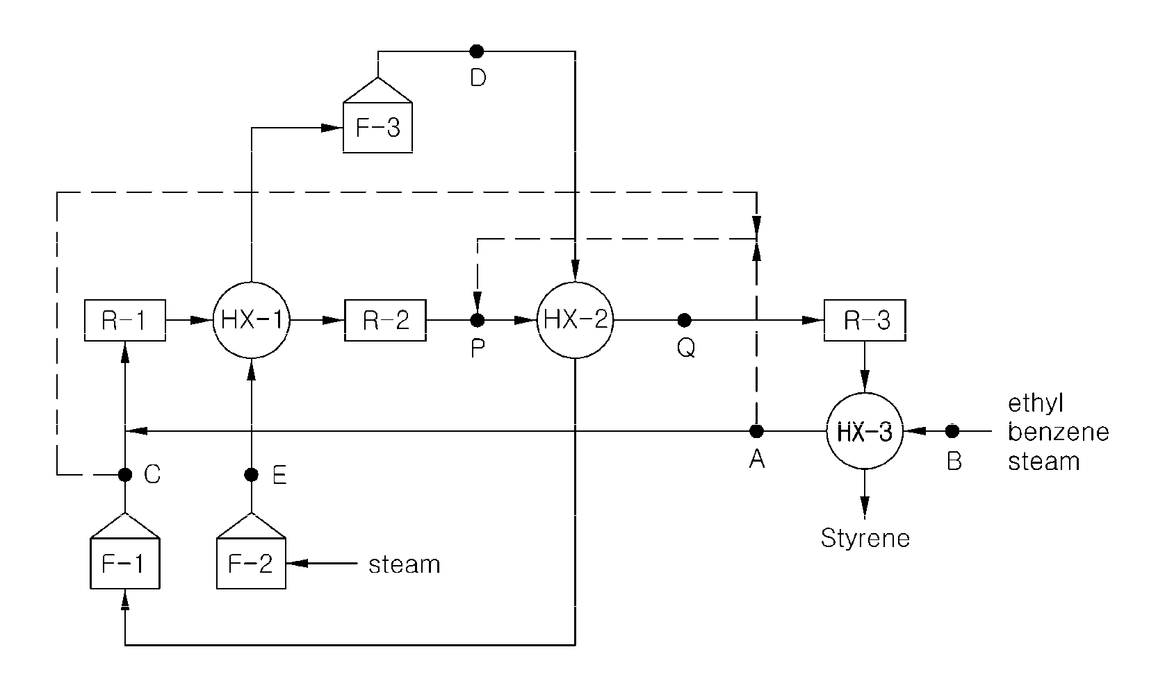
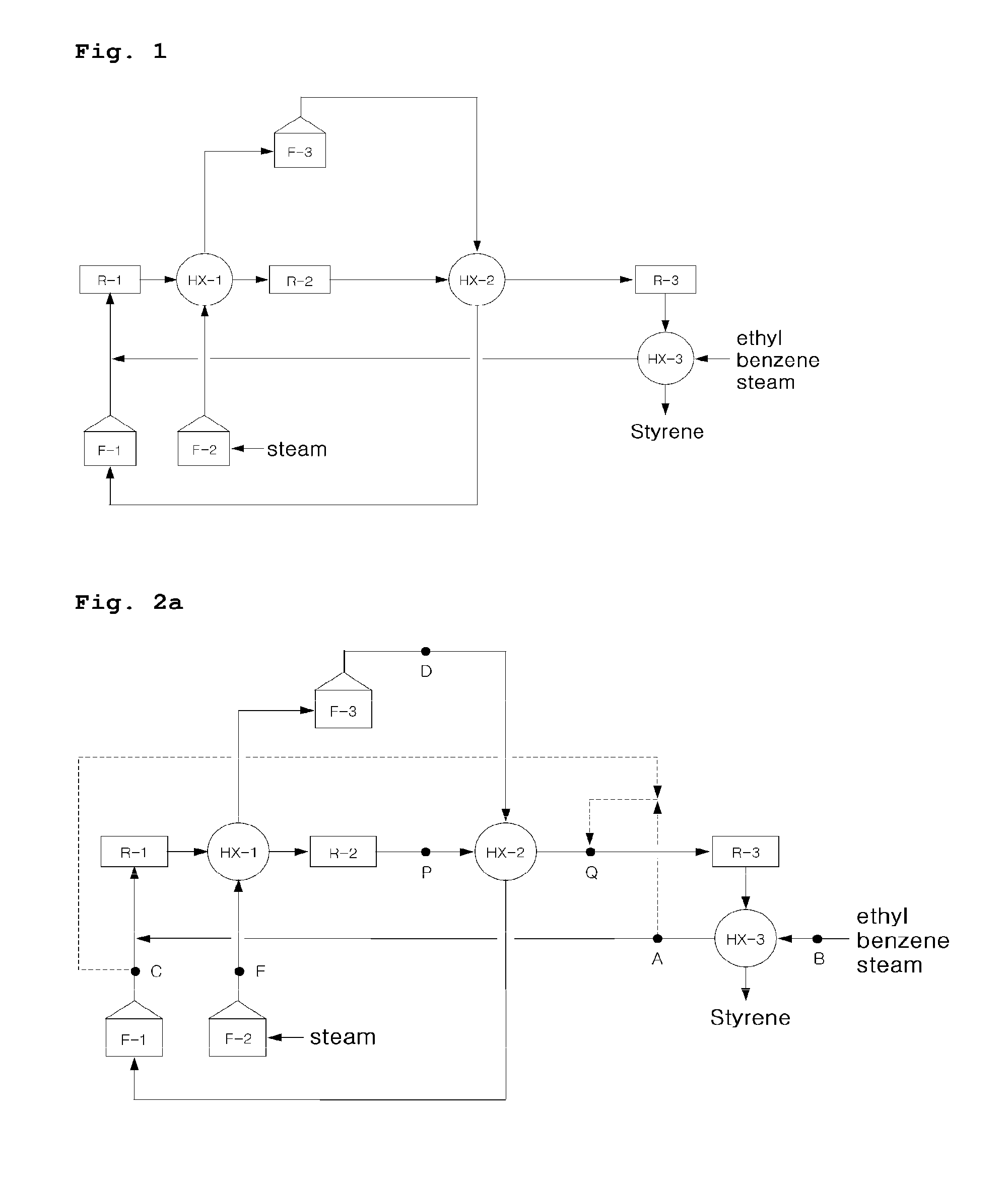
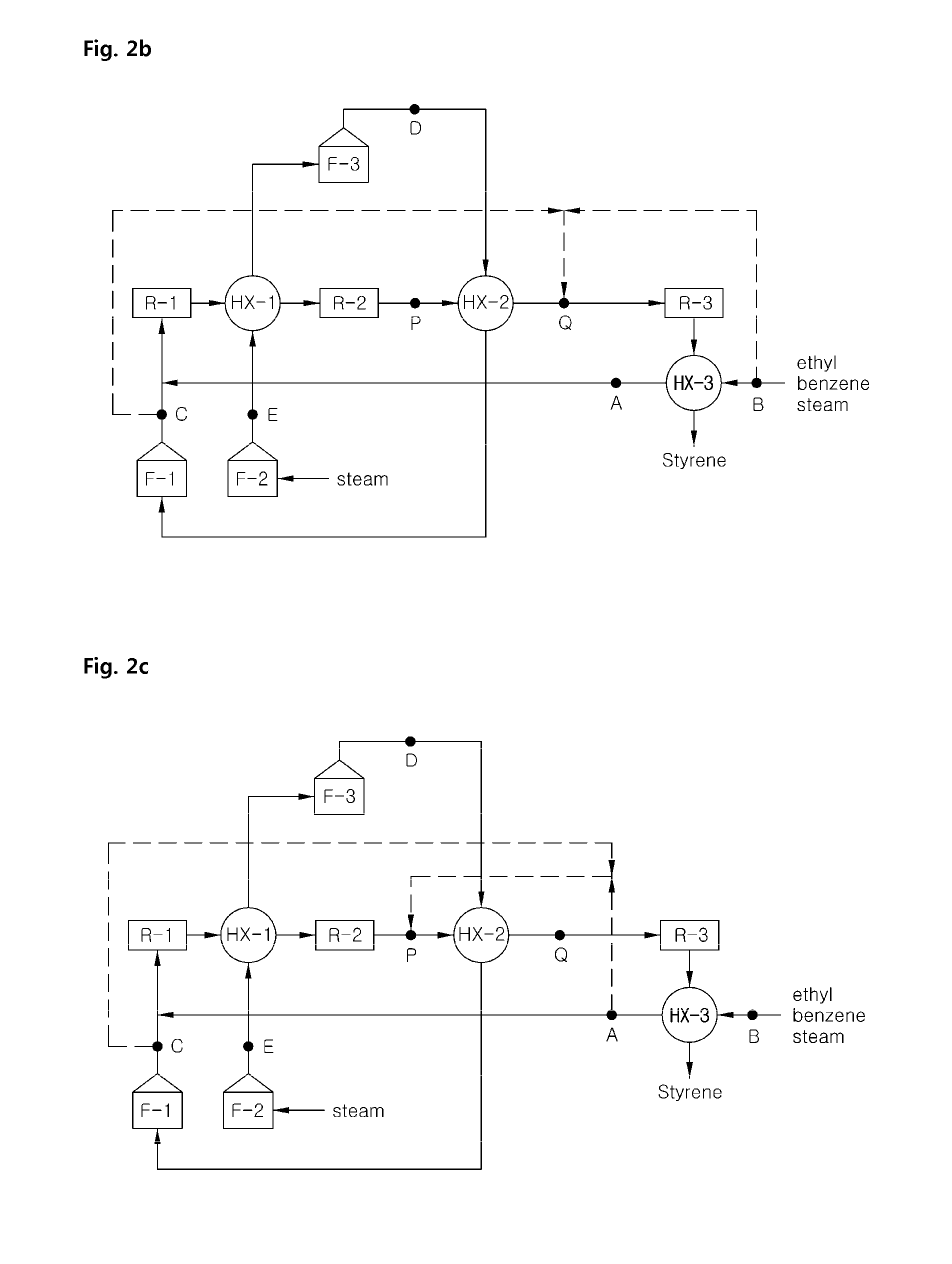
[0049]The feed containing ethylbenzene and steam diverged at the point A and the amount thereof was 17.0 vol % of the total amount of the feed being fed. The ultrahigh temperature steam was possible to diverge at the point C, D or E as shown in FIGS. 2a-2b, with the amount of 17.0 vol %.

[0050]The divergence at the point C is considered to be most advantageous in theory, since the point C directly affects HPT of F-1 with same degree of effect, although the point D directly affects HPT of F-1 and F-3, and the point E directly affects HPT of F-1, F-2 and F-3. In the above, the ‘directly affects’ means reduction in heat supply or heat exchange capability due to reduction in the feed amount caused by the divergence. Such reduced capability results in direct increase in HPT. The tendency and the degree of temperature change was estimated and compared through simulation.

[0051]The case 1 in which only ultrahigh temperature steam diverged...

experiment example 2

Injection of the Diverged Amount of the Feed and Ultrahigh Temperature Steam

[0054]The point P or point Q in FIGS. 2a-2e is the point for possibly injecting the ultrahigh temperature steam, and the raw materials, i.e. ethylbenzene and steam diverged.

[0055]It is difficult to determine which point between the point P and point Q is more advantageous, theoretically. For selecting the more preferred injection point, the different effects of the injection point P and point Q on HPT of F-1, F-2 and F-3 (i.e., by the equation of (HPT at the position P-HPT at the position Q)) were simulated and compared, with a given divergence point of the point C for ultrahigh temperature steam. The results were summarized in the following Table 2.

[0056]

TABLE 2FurnaceF-1F-2F-3(HPT at the position P - HPT0.00.04.0at the position Q) ° C.

[0057]From the results of Table 2, although the injection point of the point P or point Q only had small influence on HPT of F-3, the point Q was more preferred.

[0058]However...


PUM

PropertyMeasurementUnit
temperatureaaaaaaaaaa
vol %aaaaaaaaaa
temperatureaaaaaaaaaa

Abstract

A method for improving productivity and process stability in styrene monomer manufacturing system using a reaction system having multiple reactors connected in series, which can prevent destruction of the embedded catalyst and bending of a screen which supports catalyst and achieve homogeneous catalyst inactivation during the reaction by divergence of some portions of the feed containing steam and ethylbenzene and injection thereof into a certain point of the system.

Description

FIELD OF THE INVENTION[0001]The present invention relates to a method for improving productivity and process stability in styrene manufacturing process via catalytic dehydrogenation of ethylbenzene in the presence of steam by enhancing the feeding method of the feed.BACKGROUND OF THE INVENTION[0002]Styrene, a raw material for major polymer products such as polystyrene, ABS, SBR and the like, is consumed at more than 30 million tons per year worldwide with an increasing demand at a rate of up to 3%, thereby being one of the representative general-purpose monomer products.[0003]It is well-known in the field of chemistry that styrene can be prepared by dehydrogenating ethylbenzene in the presence of overheated water vapor, i.e., steam on a dehydrogenation catalyst bed in a reactor. Such a styrene preparation process is an endothermic reaction that occurs under a high temperature condition, and thus is regarded to be one of the representative great energy-consuming processes. As for the...

Claims


Application Information

Patent Timeline
Patent Type & Authority Patents(United States)
IPC IPC(8): C07C5/327
CPCC07C5/333C07C15/46
Inventor WON, JONG-KUKJANG, HEE-HEON
Owner HANWHA TOTALENERGIES PETROCHEMICAL CO LTD
Why Eureka
Try Eureka