CMOS compatible silicon differential condenser microphone and method for manufacturing the same

a technology of silicon differential condenser and microphone, which is applied in the field of microphone technology, can solve the problems of reducing the size of the microphone, deteriorating the performance of the diaphragm, and less conformity of the diaphragm, so as to achieve the effect of increasing the signal-to-noise ratio of the microphon

Active Publication Date: 2014-10-14
GOERTEK MICROELECTRONICS CO LTD
View PDF17 Cites 25 Cited by
  • Summary
  • Abstract
  • Description
  • Claims
  • Application Information

AI Technical Summary

Benefits of technology

[0010]In order to solve the above problems, the present invention provides a CMOS compatible silicon differential condenser microphone and a method for manufacturing the same. With this CMOS compatible silicon differential condenser microphone, the signal-to-noise ratio of the microphone can be increased. Further, such a differential capacitive microphone sensor is compatible to CMOS processing, and can be fabricated and integrated with pre-amplifiers and / or differential amplifier integrated circuits as a monolithic chip.

Problems solved by technology

Reducing the size of the microphone may deteriorate its performance, such as sensitivity.
This double diaphragm structure is disadvantageous in that it gives common mode change in capacitance, and the diaphragms are less compliant in case pillars are provided therebetween.
However, this structure may not be suitable for integration with CMOS circuitry and / or flip-chip bonding.
However, this structure cannot be CMOS compatible because of the three low stress poly silicon layers.
The microphone is characterized in that it obviates the need for creating a backside chamber, however, the rock of the diaphragm depends on sound wave direction, and there is no perforated backplate for reduction of air damping.
Also, such structure may not be proper to be integrated with other CMOS conditioning circuits.

Method used


Image

  • CMOS compatible silicon differential condenser microphone and method for manufacturing the same
  • CMOS compatible silicon differential condenser microphone and method for manufacturing the same
  • CMOS compatible silicon differential condenser microphone and method for manufacturing the same

Examples


first embodiment

The First Embodiment

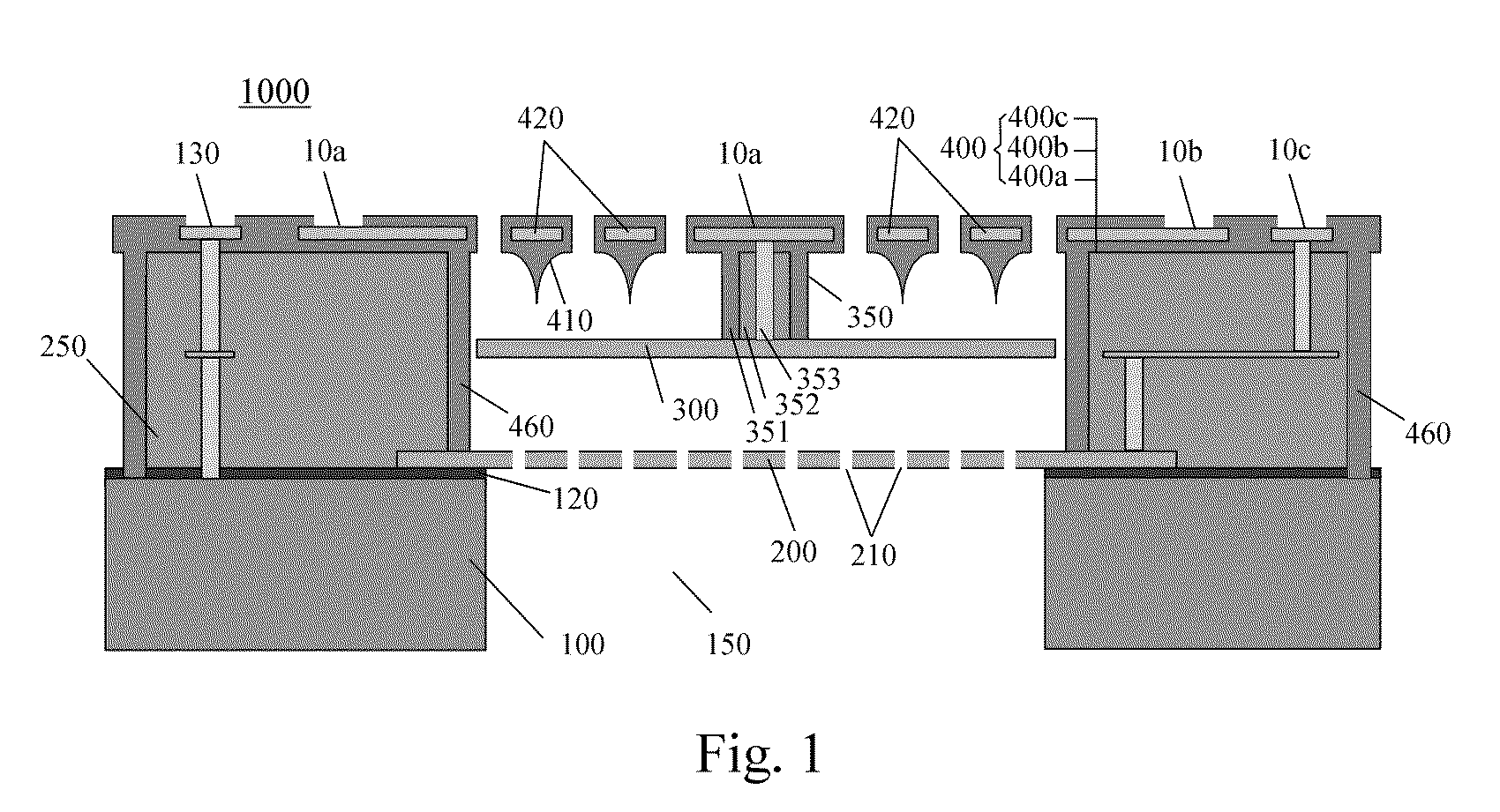
[0023]Thereinafter, the structure of the CMOS compatible silicon differential condenser microphone according to a first embodiment of the present invention will be described with reference to FIG. 1.

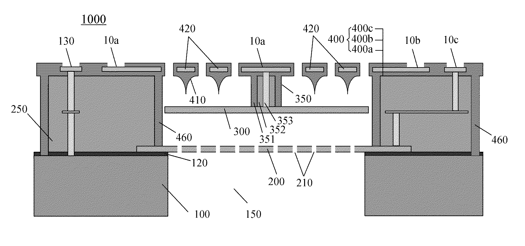
[0024]FIG. 1 is a cross-sectional view showing the structure of the CMOS compatible silicon differential condenser microphone 1000 according to the first embodiment of the present invention. As shown in FIG. 1, the CMOS compatible silicon microphone 1000 according to the first embodiment of the present invention may include a silicon substrate 100, a lower backplate 200, a spacer 250, a compliant diaphragm 300, an interconnection column 350, and an upper backplate 400. The diaphragm 300 and the lower backplate 200 form a lower variable condenser, the diaphragm 300 and the upper backplate 400 form an upper variable condenser, and the lower variable condenser and the upper variable condenser form differential condensers.

[0025]The silicon substrate 100 is used to support...

second embodiment

The Second Embodiment

[0060]Now, the structure of the CMOS compatible silicon differential condenser microphone 1000′ according to the second embodiment of the present invention will be described with reference to the FIG. 4. Comparing FIG. 4 with FIG. 1, the second embodiment of the present invention is distinguished from the first one only in that, in the second embodiment, the outskirts of the diaphragm 300 are suspended to the upper backplate 400, the interconnection column 350 connecting the center of the diaphragm 300 to the upper backplate 400 in the first embodiment as shown in FIG. 1 becomes interconnection walls 350′ located at outskirts of the diaphragm 300 in the second embodiment as shown in the FIG. 4, and a via metal 353′ is formed in the spacer 250, connecting the outskirts of the conductive diaphragm 300 to the extraction electrode 10a formed in the upper backplate 400 so as to wire out the diaphragm 300. The remaining portions of the CMOS compatible silicon differen...


PUM

PropertyMeasurementUnit
conductiveaaaaaaaaaa
perimeteraaaaaaaaaa
thicknessesaaaaaaaaaa

Abstract

The present invention provides a CMOS compatible silicon differential condenser microphone and a method of manufacturing the same. Said microphone comprises a silicon substrate, wherein a CMOS circuitry is accommodated thereon; a first rigid conductive perforated backplate supported on the silicon substrate with an insulating layer inserted therebetween; a second rigid perforated backplate formed above the first backplate, including CMOS passivation layers and a metal layer sandwiched between the CMOS passivation layers as an electrode plate of the second plate, wherein an air gap, with a spacer forming its boundary, is provided between the opposite perforated areas of the first backplate and the second backplate; a compliant diaphragm provided between the first backplate and the second backplate, wherein a back hole is formed to be open in the silicon substrate underneath the first backplate so as to allow sound pass through, and the diaphragm and the first backplate form a first variable condenser, the diaphragm and the second backplate form a second variable condenser, and the first variable condenser and the second variable condenser form differential condensers.

Description

BENEFIT CLAIMS[0001]This application is a US National Stage of International Application No. PCT / CN2011 / 071741 filed 11 Mar. 2011.FIELD OF THE INVENTION[0002]The present invention relates to the field of microphone technology, and more specifically, to a CMOS compatible silicon differential condenser microphone and a method for manufacturing the same.BACKGROUND[0003]The silicon based MEMS microphones extensively used in hearing aids, mobile phones, digital cameras and toys are being pushed to their limits. The need is endless for a smaller, cheaper, robust microphone with a high sensitivity and a low noise level. Reducing the size of the microphone may deteriorate its performance, such as sensitivity. However, nowadays, micro-processing technologies provide a very good control over crucial dimensions and properties of the microphones, making further miniaturization and optimization of the microphone possible. Also, more complicated MEMS microphone principles can be applied, such as ...

Claims


Application Information

Patent Timeline
Patent Type & Authority Patents(United States)
IPC IPC(8): H01L29/84G01P15/08H04R23/00G01L9/00B81B3/00B81C1/00H04R19/04
CPCB81B3/0078H04R19/04B81C1/00246B81B2207/015H04R19/005
Inventor WANG, ZHE
Owner GOERTEK MICROELECTRONICS CO LTD
Why Eureka
Try Eureka