
Gas dispersion apparatus for improved gas-liquid mass transfer

a gas-liquid mass transfer and gas-liquid technology, which is applied in water/sewage treatment by degassing, separation processes, filtration separation, etc., can solve the problems of increasing the solubility of ozone in water, and faster rise of ozone for tertiary treatment of wastewater

Active Publication Date: 2014-10-28
AIR PROD & CHEM INC
View PDF19 Cites 0 Cited by
  • Summary
  • Abstract
  • Description
  • Claims
  • Application Information

AI Technical Summary

Benefits of technology

This approach enhances ozone transfer efficiency, reduces energy consumption, and allows for wider operating ranges, making it suitable for large-volume water treatment plants, while maintaining high ozone utilization rates even at higher water pressures, thus overcoming the limitations of traditional methods.

Problems solved by technology

This application of ozone for the tertiary treatment of wastewater is rising faster than the other uses of ozone due to water scarcity and concerns over the impact of EDCs on aquatic life.
The high ozone concentration reduces the amount of gas that has to be handled in the gas-liquid mixing apparatus and increases the solubility of ozone in the water.
Operating the process at higher than the atmospheric pressure also increases the solubility of ozone in water.
The residual ozone in the effluent gas stream from the process represents the energy that is wasted in the ozone generator and results in increased oxygen costs.
At higher pressures, the energy efficiency and generating capacity of corona discharge generators is reduced, making it more expensive to produce ozone at pressures greater than 15 psig (103.4 kPa).
Downstream of the eductor, mixing is inefficient and provides only limited additional mass transfer.
The minimum velocity required is specific to the static mixer and results in a large pressure drop across the mixer, thus increasing the energy requirements for the process.
This reduces the ozone mass-transfer efficiency in the contactor.
As ozone gas generation is the major cost of the process, the reduced ozone mass-transfer efficiency in the contactor makes the process less economical.
The lack of proper mixing due to reduced gas flow also leads to non-uniform distribution of ozone in the basin, and could reduce the CT below that required by the relevant water-disinfection regulations.
The use of a large fraction of high-purity oxygen increases the unit cost of treating water and results in a waste of energy during periods of low ozone demand.
Another drawback to the use of a basin contactor is that the fine pores in the gas diffuser (often micron size) clog over time, and thereby significantly affect the performance of the contactor.
Clogging of the diffusers requires that they be cleaned or replaced periodically, leading to process downtime and increased maintenance costs.
The treatment of wastewater is also a greater challenge for the traditional fine-bubble diffuser-based basin contactor method as the wastewater carries a higher concentration of the fine suspended solids in it that lead to frequent clogging of the diffuser and poor performance in the contactor.
Water flow rates in both drinking water and wastewater treatment plants vary significantly during the day and over the seasons, which makes operation of most traditional contacting methods expensive during low ozone-demand periods.
Other disadvantages of the diffuser-based process include that: large, deep basins are required for effective transfer of ozone to water, thus increasing costs and space requirements; channeling of gas bubbles reduces the efficiency of mass transfer; and the process is not amenable to high-pressure operation, which would increase the dissolution of the ozone gas in water.
This venturi-based method can only be used effectively in systems with relatively low water flow rates.
The diverted stream venturi method is typically only effective for relatively low-dose ozone transfer (e.g., 10 mg / L or less).
The high velocity of the two-phase jet required for effective mixing and mass transfer of ozone in the main flow leads to a high pressure drop across the injection nozzles.
This requires high gas-liquid velocity through the static mixer which results in a higher pressure drop across it than any other process of gas dissolution.
The efficiency of the ozone transfer suffers dramatically when the water flow rate is reduced below the optimum operating range for the static mixer.
This is a huge challenge for the plant operations because in drinking water and wastewater plants the water-flow rate changes considerably with demand during the day and over the seasons.
Turbine contactors do not appear to be well-suited to ozone transfer applications for several reasons.
In addition, the ratio of ozone gas to water entering the turbine contactor must be kept relatively constant for efficient operation, which limits the ability to adjust ozone dosing.
Turbine contactors are not well-suited for catalytic ozonation because the powdered catalyst will plug the channels through which the ozone gas is aspirated.
Packed columns are rarely used for ozone transfer into liquid phase because this type of reactor has very low ozone mass-transfer efficiency, and therefore a very tall column is required to achieve typical ozone dosing.
Packed columns can be used for fixed bed catalytic reactions with ozone but, due to low mass-transfer efficiency of ozone, are expensive to build and operate.
The design and operation of an ozone transfer system including impinging jets is complex due to the need for precision location of the impact zones.
In addition, the jets have high power requirements and the range of flow rates that can be accommodated by this type of system is limited.
Accordingly, this method is rarely used for large-volume water treatment applications, for example drinking- and wastewater-treatment applications.

Method used


Image

  • Gas dispersion apparatus for improved gas-liquid mass transfer
  • Gas dispersion apparatus for improved gas-liquid mass transfer
  • Gas dispersion apparatus for improved gas-liquid mass transfer

Examples


Embodiment Construction

[0037]Unless otherwise stated herein, any and all percentages identified in the specification, drawings and claims should be understood to be on a weight percentage basis.

[0038]Unless otherwise stated herein, any and all pressures identified in the specification, drawings and claims should be understood to mean gauge pressure.

[0039]As used in the specification and claims, the term “flow communication” is intended to mean that two or more elements are connected (either directly or indirectly) in a manner that enables fluids to flow between the elements, including connections that may contain valves, gates, or other devices that may selectively restrict fluid flow.

[0040]As used in the specification and claims, the terms “ozone transfer,”“ozone mass transfer,” and “ozone dissolution” are all intended to refer to the dissolution of ozone gas into water.

[0041]To aid in describing the invention, directional terms may be used in the specification and claims to describe portions of the pres...


PUM

PropertyMeasurementUnit
water flow rateaaaaaaaaaa
gas pressureaaaaaaaaaa

Abstract

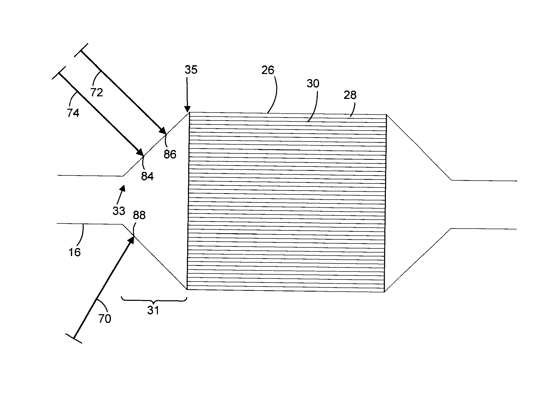
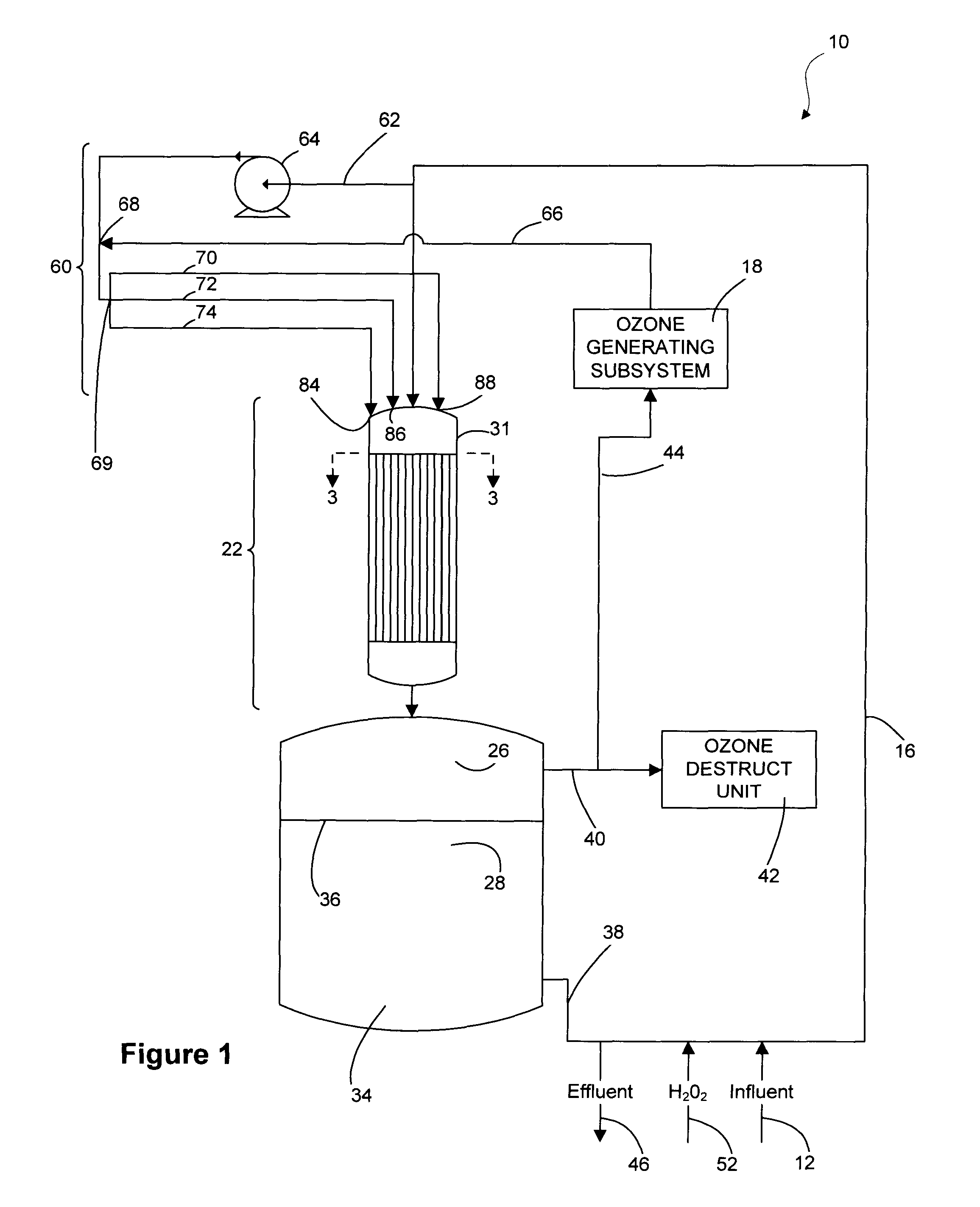
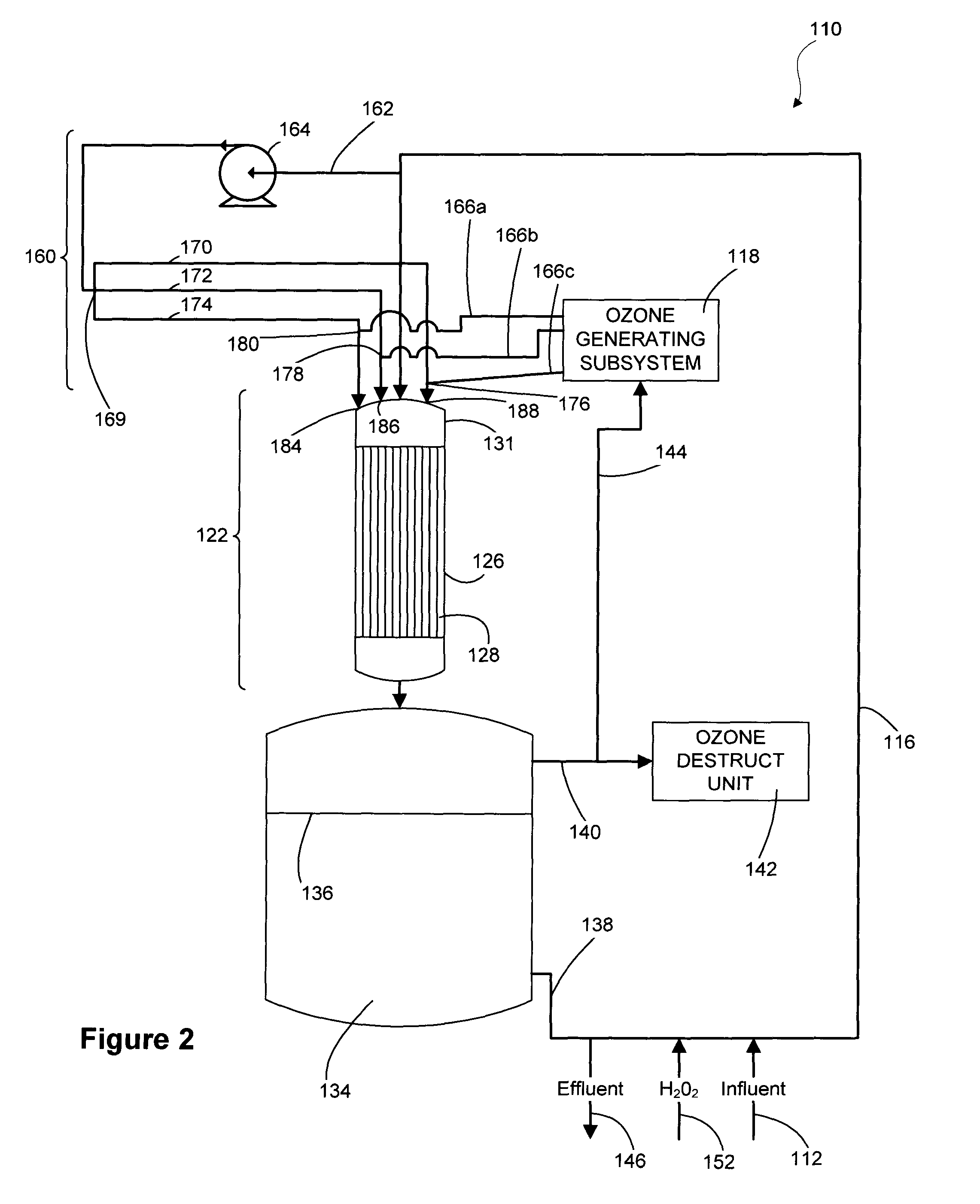
The invention discloses an apparatus and method to uniformly disperse ozone gas bubbles into liquid phase water for the treatment thereof. The apparatus consists of a water inlet section connected with a section with structured packing or monolith having parallel flow channels. A portion of the influent water is withdrawn from the main water stream as a side stream, pressurized by a pump, mixed with ozone-containing gas, and then injected back into the main water flow. The side stream may be divided into multiple streams either before or after mixing with the ozone-containing gas, and then injected into the main flow section upstream of the packed section. In alternate embodiments, the ozone-containing gas can be injected directly through the gas diffusers just upstream of the packed section in order to achieve uniform concentration of gas and liquid in the fluid entering the monolith.

Description

BACKGROUND OF THE INVENTION[0001]Ozone is a powerful disinfectant and is used to oxidize organic contaminants from drinking water, including the naturally occurring taste- and odor-causing compounds. Ozone is also used in the effluent from the secondary treatment of wastewater to remove trace organic contaminants and endocrine disrupting compounds (EDCs) from the water before reuse as indirect potable water or discharge to a water body. EDCs may be found in, for example, pharmaceutical residues, pesticides and herbicides, and many ingredients of personal care products. This application of ozone for the tertiary treatment of wastewater is rising faster than the other uses of ozone due to water scarcity and concerns over the impact of EDCs on aquatic life. For most applications involving treatment of drinking water or municipal wastewater, before disposal to streams and lakes the typical ozone dose is in the range of 3 mg of ozone per liter of water to 5 mg / L. The water flow rate in t...

Claims


Application Information

Patent Timeline
Patent Type & Authority Patents(United States)
IPC IPC(8): C02F101/30C02F101/36C02F1/72C02F1/78
CPCC02F1/78C02F2303/18C02F2209/03C02F2201/782C02F2201/784C02F2209/23C02F2101/306C02F2101/366C02F2209/235C02F2101/305C02F2209/40C02F1/722C02F2301/066C02F1/725B01F23/20
Inventor DHOLAKIA, VIPUL P.WEIST, ANNEMARIE OTTMITCHELL, JR., DAVID LEE
Owner AIR PROD & CHEM INC
Learn More